700A Series Portable Video Test Generators Quick Start Guide
Contents Model 700A, 701A Video Test Generators Quick Start Guide Getting Started.....................................................................................................................................................3 Computer Interfaces...........................................................................................................................................4 User Interface.........................................................................................................
Getting Started Using AC Power Use only the AC adaptor provided with the generator to avoid operator injury and damage to the generator. Using Battery Power The generator uses six AA rechargeable nickel metal hydride (NiMH) batteries, which can be recharged about 1000 times. You may use alkaline batteries instead, but not while the AC charger is connected to the generator. Only NiMH batteries can be safely recharged in the generator. All batteries in the generator must be the same type.
Computer Interfaces SDI/HD-SDI (Active on 701A only) DVI interface on 700A outputs analog signals only, using included DVI-to-VGA adaptor.
User Interface LCD Display The LCD window displays messages and menu options.
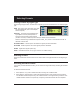
Selecting Formats Viewing Formats by Signal Type Press the Signal Type button, and then select a signal type, to list formats based on the selected signal type. VESA Red, green, blue component color video per VESA standards. (DVI-to-VGA adaptor used for outputs.) HD/SDI NTSC/PAL Composite color baseband video signal (BNC connector) and Separate Luminance and Chrominance video signals (S-Video connector) or RGB component video per NTSC and PAL standards.
Selecting Images Selecting Images Press the Image button to select from list of available test images (patterns). You cannot modify the images, or add your own images. ������������������������ ������������������������� ������������������������� ������������������������ Gating Outputs Press the Gating button to gate outputs, and to switch sync types. Note: Color gating works for all images except Ramp.
Setting Power Save Preferences Options Menu Press the Options button to set system-level options. Hot Plug:In Setting Power Save Preference When the Power Save preference is on, and the generator is on battery power, the generator will turn off after 30 minutes of no front panel activity. If the generator is running a test sequence in Burn-in mode, the Power Save preference is ignored. To set the Power Save preference, select Options > Pwr Save.
Calibrating Model 700A and 701A generators use programmable hardware to set the amplitude calibration factors for analog video outputs. These calibration factors are stored in Flash EPROM, and are not lost if the batteries are run down or removed. Quantum Data calibrates the analog video and sync output amplitudes in new generators to published specifications. You can recalibrate these amplitudes over a nominal range to meet your specific testing conditions.
Calibrating Calibrating Outputs 1. Select Options > Calibrate > Reset to set the generator’s calibration factors to default nominal values. 2. Press Options > Calibrate > Full Scale. 3. Set the voltmeter’s scale factor to be able to measure a nominal 1000 millivolts DC. 4. Using a VGA-to-BNC cable, connect the generator’s red output to the positive input on the voltmeter, with a 75 ohm (+/‑ 1%) input terminator. Connect the negative lead of the meter to any ground pin. 5.
Calibrating Locking Calibration Settings The generator uses an internal hardware jumper to enable and disable changes to calibration settings. If the Options > Calibration option is available, the jumper is set to enable re-calibration. To prevent users from changing calibration settings: 1. Turn the generator off, and remove the back cover. 2. Locate the J10 jumper, which is near the lower-right corner of the board. 3. Connect the jumper to only one pin to disable user calibration.
Detecting Formats Supported by a Monitor Learn Monitor If the generator is connected to a VESA DCCcompliant display, press the Learn Monitor button to view formats supported by both the display and generator. To view the format names, select the Details option after the generator completes reading the EDID (Extended Display Identification Data) data. The display’s EDID data may include nonVESA formats, which are not listed.
Using Test Sequences Test Menu Press the Test button to select special test operating modes. ������������� �������� ������������ �������� ������������������������ ������������������������� ����������� ������������������������� ��������������� �������� ����� ������������� �������� �������� ���� �������� ������������ �������� Running Test Sequence Manually The generator includes a test sequence, which specifies a series of format and image combinations.
Using Test Sequences Running Test Sequence in Burn-In Mode Select Test > Burn-In > Run to automatically cycle through the test sequence. When the Burn-In mode is stopped, you can use the menu buttons to gate video color information, change sync types, and turn all signal outputs on and off. NOTE: The Burn-In mode disables the Power-Save feature, if enabled.
Special Tests Testing Audio Select Test > Audio to independently toggle stereo audio output channels on and off. On a 701A generator, the left channel is also the monophonic audio source for the modulated RF output.
Special Tests Generating Pseudo Random Noise When the generator is connected to a device that supports the Quantum Data pseudo random noise standard, press Test > PR Noise to output the noise pattern as a static image. Depending on how the device is designed, it may compare the pattern output by the generator with an identical pattern, created internally, to detect errors in the cable and in the device itself.
Using Video Generator Manager About VGM Video Generator Manager (VGM) is a Windows-based application for creating and editing formats and test sequences. As many as 132 formats and one test sequence can be stored in the generator. VGM was originally created for use with Quantum Data 80x video generators. The 700A-Series generators support only some VGM features. For information about using VGM, see the VGM help file. VGM Quick Tour 1. Connect the generator to your computer using a null modem serial cable.
Creating Video Formats Editing Video Formats You can use VGM to create your own video formats. You can start with a default format in the VGM format editor, or copy an existing format. To create a video format: 1. Connect the generator with VGM, and then double-click the generator name. 2. Click the View Formats icon to list the available formats. 3. Right-click a format that is similar to the format you want to create, then select Copy to create a copy of the format.
Modifying Test Sequence Editing the Test Sequence The generator has a default sequence, which you can edit in VGM. One sequence can be stored in the generator at the same time. To modify the test sequence: 1. Connect the generator with VGM, and then double-click the generator name. 2. In the generator window, click the Sequence List icon 3. Right-click the sequence name, and then select Edit to open the Sequence Editor. 4. Select the 700A generator from the Generator list.
Pattern Descriptions Flat_Wht/(R,G,B) Description - Fills the screen with white, blue (B), green (G) or red (R). Application - Use to test chrominence. Grid Decription - White crosshatch on a black background. The lines form square boxes. A single pixel dot is located in the center of each crosshatch box. Application - Use the Grid pattern to test convergence. To accurately produce an image on a color monitor, the three electron beams in the CRT must meet (converge) at the same location at the same time.
Pattern Descriptions the entire screen, in a large portion of the screen, or localized in a very small area. Raster Description - Black display (nothing being displayed). Application - Useful for centering the raster on a CRT. Many monitor applications require that the displayed image or text fit completely within a bezel that surrounds the CRT. This usually requires that you first center the blank raster on the face of the CRT, and then center the image within the raster.
Pattern Descriptions Regulate Description - The image has a pair of white outlined boxes which surround a blinking solid white box. Application - Tests for proper high voltage regulation. Checker Description - The image’s active video area is equally divided into a 6x6 checkerboard of black and white boxes. Application - The pattern is based on a proposed ANSI method of measuring the contrast ratio of video projection systems.
Pattern Descriptions Application - Useful for testing pixel anomolies and chrominance. PulseBar Description - The image looks like two vertical lines followed by a wide vertical bar on a display’s screen. The first line is a red pulse. The pulse is 20 T for PAL and 12.5 T for NTSC formats. The second narrower line is a 2 T white sine-squared pulse. T = 100 nSec for PAL and 125 nSec for NTSC formats. The wide bar is white with sine-squared edges.
Updating Firmware Updating Firmware The generator’s operating system firmware is stored in Flash EPROM, which you can update via the serial port. Firmware updates are available from http://www.quantumdata.com/support/downloads/. To install a firmware update: 1. Turn ON the generator and connect it to your PC using a null modem serial cable. 2. Start HyperTerminal with the proper communications setup (9600 bps, 8 data bits, no parity, 1 stop bit, Xon/Xoff flow control).
Specifications Video Formats Storage: 132 total Press Signal Type button to view signal types. Edit method: Windows-based VGM software Test Images (Patterns) Digital Video Pixel rate: Audio Outputs Connecter: 3.5 mm stereo phone jack Signals: Left: 1 KHz tone Right: 2 KHz tone Press Image button to list images.
Service and Support Contacts To contact Technical Support, see http://www.quantumdata.com/contact/support.asp. For factory-authorized service centers, see http://www.quantumdata.com/contact/locations.asp. Model 700A, 701A Quick Start Guide 68-00198-D 01-Oct-2007 Copyright © 2007 by Quantum Data, Inc. All rights reserved.