® Model 801GC, 801GF & 801GX Portable Video Signal Generators Owner's and Programmer's Manual
Thank you for considering our product. At Quantum Data, we are committed to providing you with innovative products and superior customer service. If something doesn't seem right or you see an opportunity that we haven't addressed, please let us know. Helping our customer's solve their problems is what we do best. ® 2111 Big Timber Road Elgin, IL 60123-1100 USA Phone: (847) 888-0450 Fax: (847) 888-2802 BBS: (847) 888-0115 [≤19.
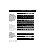
Table of Contents 1. To quickly find information on the topics shown on the right, just match the black bars with the black markers on the edges of the pages in the manual. For more information on the contents of each chapter, please refer to the table of contents starting on the next page. 2. Basic Operation 3. Built-In Formats 4. 5. Introduction Built-In Images Making Connections 6. 7. 8. Programming T r oubleshooting Error Messages 9.
Trademark Acknowledgments: Quantum Data is a registered trademark of Quantum Data Corporation. IBM is a registered trademark of International Business Machines Corporation. Macintosh and Apple are registered trademarks of Apple Computer, Inc. Microsoft and MS-DOS are registered trademarks of Microsoft Corporation. MultiSync is a registered trademark of NEC Home Electronics, Inc. Radio Shack is a registered trademark of Tandy Corporation.
Chapter 1: Introduction 1-1 Features ..................................................... 1-2 Product Overview ..................................... 1-3 Formats ................................................. 1-3 Images ................................................... 1-3 Controls ................................................. 1-3 Connectors ............................................ 1-4 Chapter 2: Basic Operation 2-1 Introduction ...............................................
Switches .................................................... 2-7 AC Select .............................................. 2-7 Power Switch ......................................... 2-7 Buttons ...................................................... 2-8 Image Button ......................................... 2-8 Video Gate Buttons ............................... 2-9 Analog Monochrome Operation ............ 2-9 Sync Gate Buttons .............................. 2-10 Outputs Button ...............................
BLU_EM, GRN_EM, RED_EM, WHT_EM, MEMESony, MESony_B, MESony_G, and MESony_R ............................................ 5-5 BLU_EM+, GRN_EM+, RED_EM+, WHT_EM+, MEMEPlus, MEPlus_B, MEPlus_G, and MEPlus_R ................... 5-6 BLU_PIC, GRAY_PIC, GRN_PIC, RED_PIC, WHT_PIC, Flat, Flat Gray, Flat_B, Flat_G, and Flat_R ............................................. 5-7 Box_50mm and Box_64mm .................. 5-9 BriteBox ............................................... 5-10 Burst ................................
Focus_Oo ............................................ 5-27 Format ................................................. 5-28 GrayBar ............................................... 5-29 Grill_11, Grill_22, Grill_33, Grill_44 ..... 5-30 Hatch_10i, Hatch_10o, Hatch_12i, Hatch_12o, Hatch_24i, Hatch_24o, Hatch_24s, Hatch_G, Hatch_M, GRN_HTCH, and MAGENTA .................................... 5-31 Hatch4x3, Hatch5x4 and Hatch8x8 ..... 5-33 Hatch64W ............................................ 5-34 Hitachi1 ..........
Regulate .............................................. 5-53 Samsung1 ........................................... 5-54 Samsung2 ........................................... 5-54 SlideG .................................................. 5-54 SlideRGB ............................................. 5-54 SMPTE133 .......................................... 5-55 SMPTEbar ........................................... 5-61 Stairs20 ............................................... 5-66 Strokes0, Strokes1 ................
Checking a Display Code ...................... 5-7 SUN Display Codes ............................... 5-8 IBM VGA Display Codes ....................... 5-8 Apple Macintosh Display Codes ............ 5-8 External Programming Connections ..... 5-9 Serial Port Connection ............................. 5-9 PC / Terminal Wiring ........................... 5-11 Apple Macintosh Wiring ....................... 5-12 IEEE-488 (GPIB) Port Connection .........
Image Knob Directory Editor ................. 6-21 Custom Image Editor ............................. 6-24 What is a Sequence? ............................. 6-35 Sequence Knob Directory Editor .......... 6-36 Sequence Editor ..................................... 6-38 Running a Sequence .............................. 6-41 Cancelling the Sequence Mode ............ 6-42 Creating your own format file ............... 6-43 Entering the format parameters ........... 6-43 ANALOG_3.CMD Listing .....................
Message Syntax .................................. 6-63 Commands .......................................... 6-63 Queries ............................................... 6-64 Output Queue ...................................... 6-64 Buffer Deadlock ................................... 6-65 The Status Byte .................................. 6-65 Requesting Service ............................. 6-65 Remote/Local Operation ..................... 6-66 IEEE-488 Status Reporting: ......................................
Directory Editor Control ........................ 6-83 Directory Memory Management ............ 6-84 System Parameter Settings ................... 6-84 Miscellaneous System Parameters ...... 6-85 Direct Processor Control (Reserved) ... 6-85 Alphabetical Listing of Commands ..................... 6-86 801G Memory (Information) Flow Diagram 6-177 Chapter 7: T roubleshooting 7-1 Power-on ................................................... 7-2 Normal power-on ...................................
Format Errors ............................................ 8-4 Invalid Data Error Messages ................. 8-4 Corrupt Data Error Messages ............... 8-5 System Error Message Summary ........... 8-6 Format Error Messages ........................... 8-7 Chapter 9: Service 9-1 New Product Warranty ............................. 9-2 User Registration Card ............................ 9-2 Product Updates ....................................... 9-3 Service Agreements .................................
Appendix A:Specifications 11-1 Model 801GC, 801GF and 801GX Specifications .................................................... 11-2 Additional Model 801GC and 801GX Specifications ................................................
Notes: xiv Table of Contents Models 801GC, 801GF & 801GX¥Rev.
Chapter 1: Introduction Features Product Overview 1-1
Features ✓ low cost ✓ portable - fits in a briefcase ✓ ultra-simple controls ✓ ultra-fast format-loading & image-drawing ✓ color NTSC and PAL compatible composite and S-video outputs on the 801GX ✓ self calibrating analog video outputs ✓ industry-standard output connectors ✓ display and edit formats on the unit under test ✓ over 100 industry-standard signal formats built-in ✓ room for up to 300 user-defined formats ✓ programmable pixel rates up to 150 MHz on the 801GC and 801GX; up to 250 MHz on the 801GF ✓
Product Overview The 801G series are low-cost portable video signal generators designed for basic testing and alignment of various types of raster-scanned displays. This manual covers the 801GC, 801GF and 801GX models. Information that mentions the “801G*” applies to all three models. Formats A format is a set of specifications that describe the video signal required by a particular type of display.
Connectors 1-4 The output connectors on the 801G* match those found on popular computers and video systems. These connectors eliminate the need for expensive and bulky conversion cables. Chapter 1: Introduction Model 801GC, 801GF & 801GX¥Rev.
Chapter 2: Basic Operation Operating Modes Displays & Indicators Knobs Switches Buttons 2-1
Introduction This chapter gives you a basic overview of the Quantum Data model 801G*’s front panel operating modes and how the displays and controls function in the normal operating mode. Other chapters in this manual cover topics that you may need to know in order to operate the unit. Please refer to the table of contents or index to locate additional specific information on how to use the 801G*.
Test Sequence Mode • Running a user defined test sequence. Each step in a test sequence combines one format and one test image. The operator can then go forward and backwards through the steps using a single knob. The 801G* can be programmed so that it automatically enters a test sequence mode on power-up. This mode of operation is suitable for a test position in a manufacturing environment where the same series of tests and adjustments need to be repeated on many identical displays.
Displays and Indicators (Normal Mode) The figure below shows a typical LCD display in the normal operating mode. Please see the “Troubleshooting” chapter of this manual if the LCD is showing different types of information. This light is on whenever the 801G*; is plugged into a live AC outlet and the power switch is ON. The horizontal scanning frequency rounded to the nearest kHz. The format’s position on the Format knob list.
Knobs Format Knob in Normal Mode The format knob is normally used to select a signal format. A format is a set of parameters that specify the video and sync signal requirements of a particular display. Format parameters include timing, sync type, video type, display size, etc. By turning the knob, you can scroll through a list of formats stored in non-volatile memory. The list includes many factory default formats. You can edit the list as well as add formats that you create.
Some of the image names in the main list may refer to a sub-set of two or more different images. The images in the sub-sets are selected by first selecting the name of the desired sub-set from the main image list. If the sub-set consists of just two images, pressing the “Image” button will toggle between the two images. The button is lit when the second image is showing. If the sub-list consists of more than two images, the “Image” button is first lighted by pressing it one time.
Switches The 801G* has two switches located on its left side. Both switches are related to AC power. AC Select This recessed slide switch sets the safe AC line voltage operating range of the generator. The “Making Connections” chapter of this manual describes the correct procedure for setting this switch ❖ Do not change the voltage selector switch setting while the 801G* is connected to the AC power line. Make sure that the switch is in the correct position before plugging in the 801G*.
Buttons The 801G* has a total of eight push-button switches, arranged into four function groups: Image, Video Gate, Sync Gate, and Outputs. All of the buttons have built-in indicators. When illuminated, a button’s function is considered on (or enabled). This section of the manual describes the functions of the buttons when the 801G* is in the normal mode of operation The buttons are used for other functions when the 801G* is operated in and a test sequence or programming mode.
Video Gate Buttons The Video Gate buttons turn individual color outputs on and off. They also control the adsdition of primary color information to the NTSC / PAL video outputs on the 801GX. • The R push-button turns all of the red video outputs on and off. • The G push-button normally turns all of the green video outputs on and off. When a 2-bit digital monochrome (MDA) signal is being generated, the G push-button turns the I (intensity) signal of the video pair on and off.
Sync Gate Buttons The buttons in this group select the type of sync signal that is used to synchronize the display. Depending on a particular format’s settings, more than one type of sync can be selected by pressing two buttons at a time. • The ACS (Analog Composite Sync) push-button causes analog sync to be output on one or more of the analog video outputs. • The DCS (separate Digital Composite Sync) push-button causes a separate digital composite sync signal (CS) to be output.
Chapter 3: Built-In Formats Introduction Format charts 3-1
Introduction The charts on the following pages list the generator’s built-in formats library. These are stored in read only memory (ROM) along with the generator’s operating code. They can be used as starting points for creating your own formats and new ones can be added to the nonvolatile RAM. A maximum of 300 formats can be stored in RAM. The same format library is used for all models in the 801G series.
The information in the charts is believed to be accurate and complete at the time that this manual was wrritten. Last minute firmware changes and new firmware releases may affect the format information stored in EPROM. Explanation of Terms Used in Charts File Name Name of the format file as saved in EPROM Video Type C3 = 3-bit digital color C4 = 4-bit digital color (CGA) C6 = 6-bit digital color (EGA) M2 = 2-bit digital monochrome RGB = separate red, green and blue analog color Mono = analog monochrome.
Built-in Formats File Name IBM Digital MDA_M7 HGC_text HGCgraph CGA_M14 EGA_m2 IBM_3179 IBM_3164 File Name AT&T AT&T_SVC AT&T_IVC AT&T_EVC File Name IBM Analog PGA_400 PGA_480 VGA_m1 VGA_m2 VGA_m3 VGA_m4 XGA_m4a XGA_m4b XGA_m5 XGA_m6 XGA6475 XGA1076 File Name IBM Workstation 3-4 IBM6Km1 IBM6Km2 IBM6Km3 IBM6Km4 Chapter 3: Built-In Formats Video Type M2 M2 M2 C4 C6 C3 C3 Horiz x Vert Active Pixels 720 x 350 720 x 350 720 x 348 640 x 200 640 x 350 640 x 400 640 x 400 Line Rate 18.432 18.141 18.
Built-in Formats Ð cont.
Built-in Formats Ð cont.
Built-in Formats Ð cont.
Built-in Formats Ð cont. File Name PAL Encoded Video PAL_4xSC PALTV601 PAL_TVus PAL_TVos PAL_N File Name NTSC Encoded Video NTSC_443 NTSC4xSC NTSC_601 NTSCTVus NTSCTVos File Name HDTV Component Video HDTV_1J HDTV_2J HDTV_4J HDTV_1E HDTV_2E HDTV_4E File Name Generator Diagnostics 3-8 TEST150 TEST250 Chapter 3: Built-In Formats Video Type EYC EYC EYC EYC EYC Horiz x Vert Active Pixels 910 x 574 720 x 574 768 x 574 640 x 480 910 x 574 Line Rate 15.625 15.625 15.625 15.625 15.625 Frame Rate 25.
Chapter 4: Built-In Images Description of the test images and how to use them 4-1
Introduction This chapter covers all of the built-in test images (patterns) in a standard model 801G* generator. It is also possible to add custom, user defined test images to thegenerator. Information on modifying and adding custom test images can be found in the “Programming” chapter. Information on how to select the various images can be found in the “Basic Operation” chapter of this manual. The “Troubleshooting” chapter has information on resetting the 801GX to its factory default conditions.
ImageName Description This tells how the image is drawn on the display. A black and white drawing of the image is included as part of the description. Drawing of the Image Test Name of the test to be done The name of the test describes the type of test to be done.
Descriptions of the Images Acer1 Description Special test image specified by some display manufacturers. Consists of two sets of color bars and five blocks of “#” characters on a white crosshatch witha black background. Acer2 Description Special test image specified by some display manufacturers. Consists of colorbars, lines of “#” characters and a green border. Acer3, Acer4, Acer5 and Acer6 Description Special test images specified by some display manufacturers.
BLU_EM, GRN_EM, RED_EM, WHT_EM, MEMESony, MESony_B, MESony_G, and MESony_R Description In the primary version, the screen is filled with blue (BLU and B), green (GRN and G), red (R), or white (WHT and MEMESony) EM characters on a black background. A bit map of a single character is shown here. Only the white character has a secondary version. It’s drawn with black characters on a white background.
BLU_EM+, GRN_EM+, RED_EM+, WHT_EM+, MEMEPlus, MEPlus_B, MEPlus_G, and MEPlus_R Description In the primary version, the screen is filled with blue (BLU and B), green (GRN and G), red (R), or white (WHT and MEMEPlus) EM character block on a black background. A bit map of a single character block is shown here. Only the white character has a secondary version. It’s drawn with black characters on a white background.
BLU_PIC, GRAY_PIC, GRN_PIC, RED_PIC, WHT_PIC, Flat, Flat Gray, Flat_B, Flat_G, and Flat_R Description A solid blue (BLU), gray, green (GRN), red, or white (WHT) box fills the active video area. Only the white fill has a secondary version. It can be changed to a black fill. Test Purity adjustment Purpose To produce correct colors in a displayed image, the electron beams from each of the three (3) guns in the CRT should strike only their matching phosphors.
BLU_PIC, GRAY_PIC, GRN_PIC, RED_PIC, WHT_PIC, Flat, Flat Gray, Flat_B, Flat_G, and Flat_R — contd. Method The methods used for adjusting purity on a color monitor depend on the type of monitor and CRT you’re using (for example; Delta, In-Line or Single Gun). In most cases, the first step is to degauss the CRT. Note – For a Delta Gun CRT, turn on only the Red output. A solid uniform field of red should be displayed. If the color is not uniform, adjust the yoke and the Purity Tabs assembly.
Box_50mm and Box_64mm Description The primary version has a solid white box in the center of the active video. Depending on the image selected, the box is either 50 millimeters (1.97 inches) or 64 millimeters (2.52 inches) square. If there’s room, information on the current format appears below and to the left of the box. This shows the number of active pixels and lines as well as the horizontal and vertical scan rates. An I after the number of active lines indicates the format is interlaced.
BriteBox Description The primary version has a single white box in the center of active video. The box size is controlled by the MSIZ system parameter. The secondary version (shown below) adds four boxes in the corners of active video. Test Brightness control adjustment Purpose The wrong brightness setting may cause other tests such as Contrast, Focus and Beam Size to be invalid. An accurate brightness setting helps give repeatable measurements throughout other tests.
BriteBox — contd. Test Brightness uniformity Purpose The light output of most picture tubes varies slightly when measured across the CRT face. This test can be used to verify that the light output variation is within your spec limits. Method Select the inverted version and perform the Brightness Control Adjustment test on the center box. Then center the light meter probe in each of the corner squares and note the reading you get for each square.
(TV formats only) Burst Description: The left side start with reference white (+100 IRE) and black (+7.5 IRE) levels. This is followed by six bursts of sine waves. Each burst is at a different frequency forming vertical lines of various widths. The frequencies, going from left to right, are 0.5, 1, 2, 3, 3.58 and 4.43 MHz. Test: Frequency Response Method: When viewed on a TV screen, the peak intensities of the all of the bursts should match the white reference level.
Check511 Description Five small boxes are placed in the corners and at the center of active video. The boxes are on a black background. Each box consists of alternating black and white pixels that form a very fine checkerboard. The secondary version inverts the image, creating a white background. The colors of the individual pixels in the boxes also are inverted. Test Verify monitor resolution Purpose The resolution of your monitor should meet or exceed the design specs.
CheckBy3 Description The active video area is equally divided into a three by three checkerboard of black and white boxes. The primary version has four white boxes as shown in the figure on the left. The secondary version has five white boxes as shown in the figure on the right. Test Contrast ratio Purpose The pattern is based on a proposed ANSI method of measuring the contrast ratio of video projection systems.
Check_11 Description The active video area is filled with alternating black and white pixels that form a very fine checkerboard. The secondary version inverts the colors in the image. The inverted image looks almost the same as the non-inverted version. Test Verify monitor resolution Purpose The resolution of your monitor should meet or exceed the design specs. Method Adjust the brightness, contrast, and focus to their correct settings first.
CirclesL Description This image may be called for by some display manufacturers’ test procedures. The image consists of five large white circles on a black background. The circles are positioned in the center and in the corners of the active video area. The secondary version inverts the image to black circles on a white background. Purpose 4-16 This pattern is specified by one or more monitor manufacturers for checking and adjusting video scan size, linearity and over scanning.
CirclesS Description This image may be called for by some display manufacturers’ test procedures. The image consists of eight small white circles on a black background. The circles are positioned in the corners of the active video area and centered on each edge of the active video area. The secondary version inverts the image to black circles on a white background.
ColorBar Description The primary version has 16 full-height vertical color bars. The order of the bars is shown below. The secondary version splits the field into a top and bottom half. The bars in the bottom half of the screen are in reverse order.
Cubes Description This is an animated image consisting of one small multicolored cube orbiting around a larger multicolored cube. Each cube also is spinning on its own axis. The default text string says Quantum Data. The text can be modified and saved using commands sent over the communications ports. The primary version has a black background and a thick green border. The secondary version uses just a white background. Quantum Data Purpose Can be used for show demonstrations with your own text.
Custom Description This image has a white border around the active video, a centered smaller yellow box, and green diagonals. Purpose This image is an example of some of the available drawing primitives. It’s not intended to be an image suitable for testing or adjusting a display. Rather, it can be used as a starting point for developing a custom image of your own. 4-20 Chapter 4: Built-In Images Model 801GC, 801GF & 801GX¥Rev.
Dot_10, Dot_12, Dot_24 Description The active video area is filled with multiple rows of white single pixel dots. The dots define the corners of what would appear to be square boxes if all the connecting pixels were lit. The number of rows of boxes and the number of boxes per row depends on which version of the image is selected and the screen aspect ratio of the currently loaded format.
Dot_10, Dot_12, Dot_24 — contd. Purpose In order to accurately produce an image on a color monitor, the three electron beams in the CRT must meet (converge) at the exact same location at the same time. Small dots displayed on a misconverged monitor appear as a group of multicolored dots. Method The convergence adjustments of most color monitors fall into two main categories. The first set of adjustments, usually called Static Convergence, aligns the three beams in the center of the display.
EMITest1 Description Special test image used for Electro-Magnetic Interference (EMI) testing of displays. The entire active video area is filled with a small “H” character. The primary version of the image draws white characters on a black background. The secondary version draws black characters on a white background. EMITest2 Description Same as EMITest1 but with the bottom row of characters contstantly being drawn left to right and then cleared.
Focus_@6, Focus_@7, Focus_@8 Description In the primary versions, the screen is filled with white “@” characters on a black background. Bit maps of a single character for the three different images are shown here. The secondary versions are drawn with black characters on a white background. Test Focus adjustment(s) Purpose An out-of-focus monitor displays fuzzy graphic images and poorly formed, hard-to-read text characters.
Focus_Cx Description In the primary version, the screen is filled with white Cx characters on a black background. A bit map of a single character is shown here. The secondary version is drawn with black characters on a white background. Test Focus adjustment(s) Purpose An out-of-focus monitor displays fuzzy graphic images and poorly formed, hard-to-read text characters. Method On monitors with a single (static) focus adjustment, adjust the control for the best average focus over the entire screen.
Focus_H Description In the primary version, the screen is filled with white H characters on a black background. A bit map of a single character is shown here. The secondary version is drawn with black characters on a white background. Test Focus adjustment(s) Purpose An out-of-focus monitor displays fuzzy graphic images and poorly formed, hard-to-read text characters. Method On monitors with a single (static) focus adjustment, adjust the control for the best average focus over the entire screen.
Focus_Oo Description In the primary version, the screen is filled with white Oo characters on a black background. A bit map of a single character is shown here. The secondary version is drawn with black characters on a white background. Test Focus adjustment(s) Purpose An out-of-focus monitor displays fuzzy graphic images and poorly formed, hard-to-read text characters. Method On monitors with a single (static) focus adjustment, adjust the control for the best average focus over the entire screen.
Format Description A listing of the data contained in any format. This pattern works best at display resolutions of at least 640 pixel by 480 lines. It’s quite similar to the format editor’s GUI screen. Name: MDA_m7 Location: 13 Entry Units: Time Pixel Rate: 16.257 MHz Horizontal KHz* pixels pixels pixels inches pixels pixels Rate: 18.432 Active: 720 44.289 Blank: 162 9.965 Period: 882 54.253 Physical size: 11.811 300.000 Pulse delay: 9 0.554 Pulse width: 144 8.
GrayBar White (100% Gray) 93% Gray 87% Gray 80% Gray 73% Gray 67% Gray 60% Gray 53% Gray 47% Gray Perform the Brightness Control Adjustment and Brightness Uniformity tests first. 40% Gray Method 33% Gray To check to see that a color monitor accurately reproduces colors at all intensities 27% Gray Purpose 20% Gray Video color tracking (color monitors) 13% Gray Test 7% Gray The primary version has 16 full-height vertical graybars. The intensity of the bars is shown below.
Grill_11, Grill_22, Grill_33, Grill_44 Description The entire active video area is filled with alternating black and white stripes. The stripes are drawn at different resolutions. Each of the stripes is four (4) pixels wide in the Grill_44 image and three (3) pixels wide in the Grill_33 image. Each of the stripes is two (2) pixels wide in the Grill_22 image and one (1) pixel wide in the Grill_11 image. The primary versions draw vertical stripes while the secondary versions draw horizontal stripes.
Hatch_10i, Hatch_10o, Hatch_12i, Hatch_12o, Hatch_24i, Hatch_24o, Hatch_24s, Hatch_G, Hatch_M, GRN_HTCH, and MAGENTA Description The primary versions consist of a white, green (G and GRN), or magenta (M) crosshatch drawn on a black background. The lines form square boxes. A single pixel dot is located in the center of each crosshatch box. The number of boxes formed depends on the version of the image selected and the screen aspect ratio of the currently loaded format.
Aspect Ratio W:H Decimal 16 : 9 5:3 4:3 1.777É 1.666 É 1.333 É 1:1 3:4 1.000 0.
Hatch4x3, Hatch5x4 and Hatch8x8 Description These are different versions of a crosshatch pattern that may be called for by some display manufacturers’ test procedures. The primary version consists of white crosshatch on a black background. The secondary version inverts the image to black lines on a white background. Purpose This is a general purpose test image that can be used to check and adjust video scan linearity and geometry and color convergence.
Hatch64W Description This is still another version of a crosshatch pattern that may be called for by some manufacturers’ test procedures. The primary version consists of an 8 by 8 white crosshatch on a black background. A white rectangular patch is added in the center. The secondary version inverts the image to black lines and box on a white background. Purpose 4-34 This is a general purpose test image that can be used to check and adjust video scan linearity and geometry and color convergence.
Hitachi1 Description This is a special test image specified by some display manufacturers. The image consists of a 2x2 cluster of Microsoft Windows® program manager screen simulations using Japanese characters.
KanjiKan Description In the primary version, the screen is filled with white Japanese Kan characters on a black background. The secondary version is drawn with black characters on a white background. Test 4-36 Focus adjustment(s) Chapter 4: Built-In Images Model 801GC, 801GF & 801GX¥Rev.
Linearty (Linearity) Description The image is made up of three parts. The first part consists of six (6) white circles. A large circle is drawn in the center of the screen. Its diameter equals the lesser of the video height or width of the display. A smaller circle is drawn at half the diameter and concentric with the larger circle. A circle also is drawn in each of the corners of the screen. The diameter of the corner circles equals one-fifth of the display width.
Linearty (Linearity) — contd. Detail showing center of linearity test image. All lines are one pixel thick. Test Linearity adjustment Purpose In order to present an undistorted display, the horizontal and vertical sweeps of the electron beam across the face of the CRT should be at uniform speeds. Any non-uniformity in the sweep causes portions of an image to stretch while other portions are compressed. Non-linearity in a monitor shows up in several ways.
LinFocus Description The image consists of several parts. It starts with a large circle in the center of the screen. Its diameter equals the lesser of the video height or width of the display. The second part is a 10 by 10 box crosshatch pattern. The crosshatch is drawn in from the outside edges, with any extra pixels in the boxes placed along the vertical and horizontal axis. The vertical centerline is two pixels thick if the format has an even number of active pixels per line.
LinFocus — contd. The image also includes blocks of focus-checking characters at various locations. The blocks are positioned inside the crosshatch boxes and are up to 3 by 3 characters in size. The size of the blocks is limited by the number of characters that can fit in one box. The bit map of a single focus character is shown here. 533101 /8 /7 /6 /5 /4 /3 /2 1X 2X 3X 4X 5X 6X 7X 8X The primary version consists of a white pattern on a black background.
Outline0 and Outline1 Description The Outline0 image consists of a rectangular white border on a black background. The border is one (1) pixel wide and defines the active video area. Two (2) diagonal lines join the opposite corners. A full size cross is centered in the image. The horizontal line of the cross is one (1) pixel thick for formats with an odd number of active lines and two (2) pixels thick for formats with an even number of active lines.
Outline0 and Outline1 — contd. Test Yoke tilt correction Purpose The horizontal axis of a displayed image should line up with the horizontal axis of your monitor. Any tilt is likely due to the yoke being rotated on the neck of the CRT. A rotated yoke makes any displayed image appear rotated. Method Place your monitor on a flat surface so the face of the CRT is perpendicular to the surface. Use a ruler or gauge to measure the height of each end of the image’s horizontal center line from the surface.
Test Display size correction Purpose A too-large active video size adjustment on a monitor may cause information to be lost around the edges of the screen. A too-small active video size adjustment may make some displayed information hard to read. The correct size is needed to obtain the correct aspect ratio. You need the correct aspect ratio to get round circles and square squares. Method First you need to know the correct physical size of the active video area for the display.
Outline0 and Outline1 — contd. Method Measure the lengths of the two (2) diagonal lines. Any difference is an indication of parallelogram distortion. The difference in readings should be within the specifications of the monitor. If the difference in the readings is too far beyond spec, the monitor should be rejected and sent back for repair before the operator wastes time trying to magnet a defective yoke.
Test Pin and barrel distortion correction Purpose If perfectly linear sweep signals are sent to a perfectly wound deflection yoke that’s mounted on a perfect CRT, you would not necessarily get a perfectly formed raster. Instead you would likely get a raster that had its corners stretched away from the center and resembled a pincushion. This distortion occurs because the geometry of the deflected electron beam does not match the geometry of the tube faceplate.
P1 Description 6 by 6 white crosshatch without a border on a black backgound. P2 Description 4 by 4 white crosshatch with a border on a black backgound. P3 Description 4 by 4 white crosshatch with a border and a small centered white patch on a black backgound. P4 Description 8 by 8 white crosshatch with a border on a black backgound. P5 Description 8 by 8 white crosshatch with a border and a small centered white patch on a black backgound.
Persist Description In the primary version, 15 small white boxes move back and forth between diagonal guide lines. The lines form 15 side-by-side tracks. The size of each box is scaled to the light meter box size set by the MSIZ system parameter. The box in the center track moves one scan line vertically and one pixel horizontally for each vertical frame of refresh. The seven boxes in the tracks to the right of the center track move 2, 3, 4, 5, 6, 7 and 8 pixels and lines per frame.
533101 /8 /7 /6 /5 /4 /3 /2 1X 2X 3X 4X 5X 6X 7X 8X Test Phosphor persistence Purpose The phosphors on the face of most CRTs continue to glow for a short period of time after the electron beam has stopped energizing them. This phenomenon is called persistence. A certain amount of persistence is desirable in most applications. It prevents a flickering of a displayed image that most users would find objectionable.
PulseBar (TV formats only) Description: The image looks like two vertical lines followed by a wide vertical bar on a display’s screen. The first line is a sine-squared modulated pulse that fades from black to red and back to black. The pulse is 20T for PAL and 12.5 T for NTSC formats. The second narrower line is a 2T white sine-squared pulse. T = 100 nSec for PAL and 125 nSec for NTSC formats. The wide bar is white with sine-squared edges.
QuartBox Description The primary version has a single white box in the center of active video. The size of the box is onehalf the width and height of the active video area (a quarter of the entire active video area). The secondary version draws a black box on a white background. Test Brightness control adjustment Purpose The wrong brightness setting on your monitor may cause other tests such as Contrast, Focus and Beam Size to be invalid.
Ramp (TV formats only) Description: The active video area goes from full black (+7.5 IRE) at the left edge of the screen to full white (+100 IRE) at the right edge. Test: Video Gain Linearity Method: When viewed on a TV screen, the full range of grays should be visible. There should be no color shifts visible.
Raster Description A totally black display (nothing being displayed) Test Raster centering Purpose Many monitor applications require that the displayed image or text fit completely within a bezel that surrounds the CRT. This usually requires that you first center the blank raster on the face of the CRT and then center the image within the raster. Use this image for centering the raster on the CRT. Method Turn up your monitor’s brightness control until the raster is just visible.
Regulate Description The image cycles between two (2) patterns. In the primary version, the first pattern is a white outline that defines the edges of displayed video. The other pattern has the same outline plus a solid white rectangle in the center. The size of the solid rectangle equals 95% of the height and width of displayed video. The speed of the cycle cannot be changed.
Samsung1 Description Special test image specified by some display manufacturers. The image consists of three small simulations of Microsoft WIndows® screens on a blue background. A border and centered cross are formed with repeating groups of the characters “e” and “m”. The repeating characters are also used to form a rectangular patch in the upper left hand corner and a circular area in the center of the image. Samsung2 Description Same as Samsung1 but with a black background.
SMPTE133 Description This image is based on a recommended practice (RP-133) test pattern designed by the Society of Motion Picture and Television Engineers (SMPTE). The original application was used in testing and evaluating medical imaging monochrome displays. The image now is used in many different display applications. The image is self scaling as to the number of active pixels and active lines used. Some of the image’s elements have minor differences from the original SMPTE specification.
following illustration. The patches are located in each corner of the main image and in the center. They’re oriented with the highest resolution and contrast boxes closest to the outside corners. The 48%-53%, 48%-51% and 50%-51% level patches are omitted in the secondary version. 4) Gray-Scale Boxes – Twelve (12) boxes at eleven (11) intensity levels are clustered around the center of the main image. They start at 0% and increase in 10% steps to 100% with two (2) boxes at a 50% level.
SMPTE — contd. 8) Border – A border line is drawn around the image. It’s set in from the edges of displayed video a distance equal to 1% of the displayed height and has a thickness equal to 0.5% of the displayed height. The intensity level is the same as that of the crosshatch lines. 9) Circle – A large circle is centered in the image. It touches the top and bottom of the active video area when the aspect ratio is wider than it is high (landscape-type display).
Primary version of (SMPTE) RP-133 Quantum Data 30 40 50 50 60 70 20 80 10 90 0 100 H: 720 V: 350 D: 4 Gamma Check Dither Box 2 @ 51% 2 @ 50 % Horizontal 70 1 @ 100% 1@0% Horizontal 20 80 2 @ 100% 2@0% Vertical 10 90 2 @ 100% 2@0% Horizontal 0 100 2 @ 51% 2 @ 50 % Vertical 30 2 @ 51% 2 @ 48 % Horizontal 2 @ 51% 2 @ 48 % Vertical 2 @ 53% 2 @ 48 % Vertical 2 @ 53% 2 @ 48 % Horizontal 1 @ 100% 1@0% Vertical 40 50 0% and 5% Contrast Boxes 50 60 95% and 100% Contrast Boxes 3 @
SMPTE — contd. Test Deflection linearity Method If the overall height and width of the display’s active video area match the sizes in the format, the large circle should be perfectly round. Each box in the crosshatch pattern should be the same size and shape. For more information on testing linearity, please see the discussion on the Linearty test image. Test High contrast resolution Method All the 0 and 100% level stripes in all the resolution patches should be separate and distinct.
SMPTE — contd. Test Video amplifier stability Method The two black-and-white windows should show sharp transitions between the smaller box and the surrounding window. Streaking may be an indication of undershoot or overshoot while ghost images may indicate a ringing problem. Test Excessive overscan and off-center alignment Method The entire border should be clearly visible on the face of the tube and not be hidden by the edge of the glass or by any bezel.
SMPTEbar Description: This image is based on an engineering guideline (EG 1-1990) test signal specified by the Society of Motion Picture and Television Engineers (SMPTE). The SMPTE pattern, in turn, is derived from an EIA standard test pattern (RS-189-A). The image, is set up to be generated by an 801GX as an encoded TV output. It is designed for adjusting the color settings of a television monitor by eye.
Mag Cyan Blue Red Magenta Green Cyan Yellow Gray Blue -I (Blue Gray) Gray 5% Gray Bar +Q White (Purple) SMPTEbar Image as it would appear on a TV monitor A single scan line from the upper portion of the SMPTEbar Image as it would appear on a TV waveform analyzer connected to the 801GXÕs TV output 4-62 Chapter 4: Built-In Images Model 801GC, 801GF & 801GX¥Rev.
TV Vectorscope signature of the upper color bar portion of the SMPTEbar Image using NTSC color encoding on the 801GX’s TV output TV Vectorscope signature of the lower portion of the SMPTEbar Image showing -I and Q color difference signals using NTSC color encoding on the 801GX’s TV output 4-63
Test: Color Video Performance Purpose: This general purpose pattern can be used to check the video handling capabilities of most parts of a television system. Method: When viewed on a TV screen, all of the upper color bars should be correct and in the order shown. The hue and intensity of each bar should be uniform over the entire bar. The image can be used with a TV waveform analyzer to check the performance of a video system.
The following tests are based on the original SMPTE quideline: Test: Visual Chroma Gain Adjustment Method: In order to perform this test, you must have a way of turning off the red and green guns in the monitor under test. Turning off the red and green video components of the 801GX’s video output will not work for this test. This test uses the upper and central color bars. Switch off the red and green guns on the monitor. This will produce four blue bars, separated by black bars.
Stairs20 Description The active video area goes from full black at the left edge of the screen to full white at the right edge. There are six (6) steps. The step levels are 7.5 (black), 20, 40, 60, 80 and 100 IRE. Test Video gain linearity Method When viewed on a monitor’s screen, a black bar plus five (5) gray bars should be visible. There should be no color shifts and each of the bars should be uniform in color.
Strokes0, Strokes1 Description This image may be called out by some display manufacturers’ test procedures. The Strokes0 version consists of multiple groups of separated red, green and blue horizontal lines drawn on a black background. The Strokes1 version consists of multiple groups of separated red, green and blue diagonal lines drawn on a black background. Purpose These are special-purpose test patterns used in test and alignment procedures specified by one or more display manufacturers.
Text_9, Text_16 Description In the primary versions, the screen is filled with random paragraphs of white text on a black background. The secondary versions use black text on a white background The amount of text is determined by the size of the font used and the horizontal and vertical resolution of the format. The Text_16 image uses a larger font than the Text_9 image.
Text_9, Text_16 — contd. Test Word processor simulation Purpose If your monitor is used in word processor work stations or other applications that call for large amounts of text to be displayed, you can use this image to simulate actual user conditions. Method Select a suitable font size and text color. Adjust your monitor’s brightness and contrast controls to obtain the best image. The characters in all areas of the display should be well formed and in focus.
TVBar100 & TVBar_75 (TV formats only) Black When viewed on a TV screen, all of the colors should be correct and in the order shown. The hue and intensity of each bar should be uniform over the entire bar. Blue Method: Red This general purpose pattern can be used to check the video handling capabilities of most parts of a television system. Magenta Purpose: Green Color Video Performance Cyan Test: Yellow The image consists of seven (7) vertical bars that fill the entire active video area.
1 Horizontal Period of TVBar100 Image as it would appear on a TV waveform analyzer connected to the 801GX’s TV output 1 Horizontal Period of TVBar_75Image as it would appear on a TV waveform analyzer connected to the 801GX’s TV output 4-71
TV Vectorscope signature of the TVBar_75 Image using NTSC color encoding on the 801GX. TV Vectorscope signature of the TVBar_75 Image using PAL color encoding on the 801GX. There are twice as many points as NTSC because the color sub-carrier phase is reveresed every other scan line. 4-72 Chapter 4: Built-In Images Model 801GC, 801GF & 801GX¥Rev.
TVHatch (TV formats only) Description: The image consists of a white crosshatch on a black background. The lines form square boxes when the display’s active video area has a 4:3 aspect ratio. The vertical lines are made using sine-squared (2T) pulses (T = 125 nSec for NTSC and T = 100 nSec for PAL). Test: Convergence Adjustment Purpose: In order to accurately produce an image on a color monitor, the three electron beams in the CRT must meet (converge) at the exact same location at the same time.
After the center of the display is properly converged, the outer areas can be adjusted by using the monitor’s “Dynamic Convergence” controls. The number of controls, the area of the screen that they affect and their adjustment procedure is dependent upon the monitor you’re testing. Test: Sweep Linearity Adjustment Purpose: In order to present an undistorted display, the horizontal and vertical sweeps of the electron beam across the face of the CRT should be at uniform speeds.
Chapter 5: Making Connections Line Voltage Selector AC Power Connection Display Connection Display Codes Computer Connection 5-1
Line Voltage Selector Make certain that the voltage selector switch is set correctly before plugging the 801G* in. ❖ Operating the 801G* with the wrong AC line voltage setting or adjusting the line voltage selector switch while the generator is plugged in may cause serious damage to the generator. This type of damage is not covered under the product warranty nor service contracts. You will find a recessed AC line voltage selector on the left side of the 801G* cabinet.
Fuse Requirements The 801G* uses the same AC mains fuse for all AC voltage ranges. The “Maintenance” chapter has information on the type of fuse used. AC Power Connection The power cord shipped with the 801G* is designed for use in the U.S.A. One end of this cord mates with an international-standard IEC-320 connector on the generator. The other end is compatible with most 120V/15A grounded outlets.
Display Connection We do not supply test signal cables with the 801G*. Most displays come with cabling for a particular computer. This cabling will usually be compatible with one of the connectors on the 801G*. If not, you can construct your own test cables using the information in this section. D-Sub Output Connectors The 801GC and 801GX have four D-Sub output connectors as shown in figure 5-1. The 801GF has three connectors.
Figure 5-1 D-sub Output Connectors This Connector used on 801GC and 801GX only Pin 1 2 3 4 5 6 7 8 9 10 11 12 13 14 15 (A1) (A2) (A3) MDA GND NC NC NC NC I V HS VS CGA GND NC R G B I NC HS VS EGA GND Ir R G B Ig Ib HS VS SUN GND VS M2 GND CS HS GND M1 MØ GND APPLE GND VS M2 GND CS HS GND M1 MØ GND R G B B G R VGA R G B M2 GND GND GND GND NC GND MØ M1 HS VS M3 MAC GND R CS MØ G GND M1 NC B M2 GND VS GND GND HS Table 5-1 D-Sub Output Connector Pinouts Explanation of abbreviations used in table: B
BNC Output Connectors All models have five BNC connectors along the right side as shown in figure 5-2. They are for driving analog workstation and projection displays that use RGB component video with or without separate sync(s). BNC to RCA adapter supplied with 802GX only The 801GX has a sixth connector which is used for the NTSC / PAL TV encoded video. We supply a separate BNC to RCA jack adapter (#30-00123), shown on the left, to match the connectors used on many commercial TV type monitors.
Some computers and video controller cards look for the display codes and automatically adjust their hardware to output an appropriate video signal format for the display that is connected. Checking a Display Code Problems can occur if a display outputs the wrong code and it is connected to a computer having an automatic format adjustment feature. The wrong signal may be generated and the display may appear to be broken. The 801G* is capable of checking the status of the code pins in its D-sub connectors.
SUN Display Codes The following table list the codes that are output by SUN Microsystems analog displays: Revised table not available at time of publication Table 5-3 SUN Display Codes IBM VGA Display Codes The following table list the codes that are hard-wired into IBM VGA analog displays: Display Code M3 M2 M1 M0 8512 & 8513 PS/2 Color Displays E OPEN OPEN OPEN GND 8503 PS/2 Monochrome Display D OPEN OPEN GND OPEN 8514 PS/2 Color Display A OPEN GND OPEN GND Table 5-4 IBM VGA Disp
External Programming Connections The 801G* can operated and programmed from an external computer or terminal. Two different communications ports are standard on the 801G* for a computer or terminal hook-up. The RS-232C serial port allows the unit to be connected to many personal computers or dumb terminals.The IEEE-488 (GPIB) port lets you use the 801G* as a programmable video signal source source in a larger automated test system.
Two adapters are provided for connecting the 801G* to computers and terminals that use 25 pin D-sub connectors for their RS-232 ports. One adapter (part #30-00115) allows you to attach the 801G* to a 25 pin female connector port. The other (#30-00116) adapter is for use with a 25 pin male port. The cable and adapters that are supplied with the 801G* are shown below. No other serial cables or adapters are available from Quantum Data at this time.
PC / Terminal Wiring The cable and adapters supplied with the 801G* should be suitable for most basic RS-232 hook-ups that use either 9 pin or 25 pin D-Sub connectors. In some cases, you may need to make your own special cable. The table below lists the connections required to attach the 801G* to the RS-232 port on a terminal or PC type computer.
Apple Macintosh Wiring It is possible to connect the 801G* to a serial port on a Macintosh computer. Apple uses two types of serial connectors on its Macintosh series. • The Mac Plus, SE and II have an 8 pin female mini-DIN connector. • The Mac 128, 512 and 512E have a 9 pin female D-Sub connector. The table and figure below show how to make the proper connections between the 801G* and a Mac computer using either type of connector.
IEEE-488 (GPIB) Port Connection The 801G* includes an IEEE-488 port. This port allows the 801G* to be integrated into most automated test systems that use IEEE-488 or GPIB communications between instruments. • An IEEE-488 standard 24 position micro-ribbon connector is used as a connector. • The communications protocol is per IEEE-488.2 specifications.
Notes: 5-14 Chapter 5: Making Connections Model 801GC, 801GF & 801GX¥Rev.
Programming capabilities overview Built-in GUI editors Serial & IEEE-488 programming Command Listing and Descriptions Chapter 6: Programming 6-1
Programming Capabilities Overview The 801G* video generators are powerful pieces of test equipment right out of the box. The factory default system settings give you immediate access to all of the built-in test images and built-in signal formats. However, you can program the operation of the 801G* to meet your special testing needs. The highlights of all of the 801G*’s programming features are presented in this section. Detailed information for most features will be found in following sections.
Creating custom test images User defined custom test images can be created and edited. The images are made up of one or more drawing primitives. Some of the primitives in the current firmware are single pixel dots, lines, rectangles (filled and unfilled) and ovals (filled and unfilled). The grayscale and color tables used in the image can be selected by the user. The custom test images are saved in non-volatile memory.
Setting system parameters The following system parameters are stored in the 801G*’s non-volatile system memory: • The size of the boxes used in the “BriteBox” test image. The size of the box should match the size of your light meter’s probe. The factory default size is 50.4 mm (2.00 inches) square. • The text string that appears in the upper portions of the “SMPTE133” and “Cubes” test images. The factory default string is “Quantum Data.” • The analog video outputs’ calibration factors.
be set to a higher limit if it is known that a particular unit will work reliably at the higher limit. • The gamma correction flag. This flag determines whether individual formats can control the application of gamma correction or if gamma correction is disabled regardless of a format’s setting. The factory default setting is to allow gamma correction to be controlled by individual formats.
The utility disk may also contain a text file called “README.DOC” that has information on any last minute additions and changes on programming the unit. A Microsoft Windows® compatible software interface package is also available. Please contact your Quantum Data for ordering information. Operating via remote control The 801G* can be used as a programmable video test signal source in an automated test system. The 801G* features both RS-232 and IEEE-488 communications ports.
Using the Built-In Editors You can program many aspects 801G*’s operation using the built-in Graphics User Interface (GUI). You program the 801G* by editing different file structures in the unit. The current version of 801G* firmware supports five (5) GUI editors as follows: • A Format Editor for creating and modifying test signal set-ups. • A Format Knob Directory Editor for modifying the list of formats that are selected with the “Formats” knob.
should be stable and legible on your display. You should also double check the active video data to make sure you have at least 640 pixels by 480 lines of active video. Once you have confirmed proper operation, switch the 801G* to its programming mode: 1) Turn the 801G*’s power off. 2) Turn the power back on while holding down the “Image” button on the front panel. 3) Select a compatible format using the Format knob. 4) Rotate the “Image” knob. You will see additonal image names appear on the LCD window.
Format Editor The format editor is one of the screens available in the programming mode. You can view and modify the contents of any format stored in non-volatile memory using the format editor. A typical format editor screen is shown here. The actual editor screen uses mostly lit text on a black background. Interlace Control Horizontal Parameters Hor. & Vert.
meric parameter is selected, an underscore cursor is placed below a digit in the number. The “Cursor” buttons move the digit cursor and the bottom knob changes the selected digit. In many cases, entering a new value of one parameter will affect the values of other parameters as well. The editor automaticall updates all related parameters when you enter a new value. The upper left corner shows the name and memory location number of the selected format.
The upper right corner shows the Pixel Rate. The pixel clock is the master clock used to generate all of the format’s timing information. The pixel clock period is also shown. The remainder of the top half of the screen is taken up by the horizontal and vertical parameters. These parameters deal with the output signal timing and physical size of the active video area. The names of the parameters are shown at the far left of the screen. The horizontal timing and size parameters are shown in two columns.
half the number of lines in one vertical period for interlaced formats. The current reference rate is marked with an asterisk. The Horizontal Period is always equal to the sum of the Horizontal Active and the Horizontal Blanking times. The 801G* uses two of these parameters as references to calculate the third. The last two edited parameters will always be used as the references. The current references are marked with asterisks.
Horizontal Pulse delay is the period of time from the last active pixel in a scan line to the leading edge of the horizontal sync pulse. Some display spec sheets refer to this period as the horizontal sync front porch. Horizontal Pulse width is the width of the horizontal sync pulse itself. Vertical Pulse delay is the period of time from the last active scan line to the leading edge of the vertical sync pulse. Some display spec sheets refer to this period as the vertical sync front porch.
The Scan setting determines if the video and sync timing is non-interlaced (progressive) or interlaced. Most of the bottom half of the editor screen is taken up by the video and sync type settings. The first three lines determine the behavior of the sync selection buttons. ACS kind determines what type of composite sync is added to the analog video outputs when the “ACS” button is pushed. The On setting, to the right, selects which of the component analog video outputs will have composite sync added.
• European w/serr Composite sync with serration pulses during the vertical sync period. The vertical sync delay and pulse are a half line shorter than shown. • European w/serr & EQ Composite sync with serration pulses during the vertical sync period and equalization pulses added before and / or after the vertical sync period. The vertical sync delay and pulse are a half line shorter than shown. The serration and equalization pulses occur at twice the horizontal rate.
The DS Polarity parameter, to the right of the DSS setting, sets the logical polarities of the Horizontal, Vertical and Composite digital sync outputs. Rotating the bottom knob cycles through all possible polarity combinations. A “+” setting indicatesa positive going pulse. A “-” setting indicates a negative going pulse. The DS Gate parameter, below the DS Polarity parameter, sets output gating of the Horizontal, Vertical and Composite digital sync outputs.
• Dig. V (801GC, 801GX only ) Monochrome digital (TTL) video @ 1 bit-per-pixel • Dig. VI (801GC, 801GX only ) Monochrome digital (TTL) video @ 2 bits-per-pixel (separate video and intensity bits) • Dig. RGB (801GC, 801GX only ) Color digital (TTL) video with one bit per color (black and 7 saturated colors) • Dig. RGBI (801GC, 801GX only ) Color digital (TTL) video with one video bit per color plus a common intensity bit (black, 7 saturated colors, gray and 7 dimmed colors) • Dig.
❖ Caution: Saving a format with errors in it may cause major problems when you later try to load the format. Pressing the Save or SaveAs button does NOT error check your entries. You should check your edited format for errors before saving it. Pressing the Save button saves your format the name and memory location shown at the top of the screen. unless you started with an EPROM resident format. In that case, you will be prompted for a new name. See the next paragraph for saving with a new name.
Format Knob Directory Editor Going through all of the available formats with the Format knob can be time consuming. This is particularly true if you regularly use only a few formats that may be scattered in memory. The 801G* can be set up to show only the formats you want, in the order you want, when the “Format” knob is turned. The 801G* maintains a list of these formats in non-volatile memory. This list can be edited.
The right hand side shows all of the formats that are in the 801G*. They are listed in order of ascending memory locations. Empty or corrupted memory locations are skipped. The bottom “Image” knob moves a selection box through the right hand list. The list will scroll if it can not fit on the screen. The Insert button moves the selected format in the left hand column and all of the formats below it down one line. It then copies the selected format on right hand side into the vacated position.
Image Knob Directory Editor Going through all of the available images with the Image knob can be time consuming. This is particularly true if you regularly use only a few images that may be scattered over the knob locations. The 801G* can be set up to show only the images you want, in the order you want, when the “Image” knob is turned. The 801G* maintains a list of these images in non-volatile memory. This list can be edited.
fault custom image. This image is used a starting point to creating you own custom images. Any user created custom images in non-volatile memory are at the bottom of the list. The bottom “Image” knob moves a selection box through the right hand list. The list will scroll if it can not fit on the screen. The Insert button moves the selected image in the left hand column and all of the images below it down one line. It then copies the selected image on right hand side into the vacated position.
ing it to the knob directory. Exiting the custom image editor will automatically return you to the image knob directory editor. Pressing the Done button saves the edited list and exits the editor.
Custom Image Editor There may be times when none of the 801G*’s many built-in test images (patterns) quite meet your requirements. In these cases, you may be able to create a custom image to match your exact requirements. A custom image consists of one or more simple geometric objects and alphanumeric characters (primitives). The color, relative size and relative position of the objects are all editable parameters for most of the primitives.
The right side of the screen displays the parameter currently being modified. All parameter changes are made on this side before being entered to the left side. The 801G*’s upper “Format” knob moves a selection box among the steps and parameters on the left side of the screen. The knob moves the selection box horizontally across the screen until the step number or last parameter is selected. Then the next move will be to the adjacent row. This causes a “snaking” action.
Table 4-1 Available drawing primitives in a Custom Image Primitive Name Parameters Rectangle color, width, height, left, top, fill patn Oval color, width, height, left, top, fill patn Line color, x1, y1, x2, y2 Dot Grid color, x, y color, # of xboxes, # of yboxes H-Grill color, line width V-Grill color, line width Characters color, character #, font# Limits color CenterMark color Triangle Format color, x1, y1, x2, y2, x3, y3, fill patn color, left x, top y Hatch_I-O color, # of xboxe
Table 4-3 Fill patterns in a Custom Image The “fill patn” parameter determines if a primitive is drawn as a one pixel thick outline or as a pattern filled object. Fill patterns consist of various on-off pixel combinations in a repeating 16 x 16 pixel block. A setting of “graypatn0” has all fill pixels turned off and a setting of “graypatn100” has all pixels on.
The Rectangle primitive draws a rectangle whose sides are parallel to the vertical and horizontal axis of displayed video. The primitive uses six (6) parameters. The first is the color. The next two parameters are the width and height of the rectangle in pixels. The second two parameters are the X and Y coordinates for the top left-hand corner of the rectangle. The last parameter is the fill flag.
The Line primitive draws a line between any two points. The line is one pixel thick. The primitive uses five(5) parameters, the color and the X and Y coordinates for both endpoints. The following example draws a yellow line between a point 20 pixels to the right and 5 pixels below the top left corner of active video and a point 320 pixels to the right and 240 pixels below the top left corner of active video: Line Yellow 2Ø 5 32Ø 24Ø The Dot primitive draws a single pixel dot.
The V-Grill primitive draws equally spaced vertical lines that form a grill over the entire active video area. The gap between the lines is equal to the thickness of the lines. The gaps are not touched and will show any previously drawn primitives. The primitive uses two (2) parameters. The first is the color of the lines. The second is the thickness of the lines.
The primitive uses three (3) parameters. The first is the color. The second parameter is the code number of the character. For most alpha-numeric fonts, the character number will be the same as the decimal ASCII code number of the character. The last parameter is the number of the font library. The current firmware includes ten font sets. The fonts are described in the table on the previous page. Font sets #Ø and #1 have a full set of ASCII upper and lower case letters plus numbers and punctuation marks.
a series of joined filled triangles. The following example draws a 50% red filled triangle that looks like an arrowhead pointing to the right near the top left corner of active video: Triangle Red50 10 5 10 25 40 15 1 The Format primitive shows some basic information about the format that is driving the display. The first line shows the number of horizontal active pixels and vertical active lines.
larger. The following example draws a yellow crosshatch that has 15 boxes horizontally and 9 boxes vertically: HatchI-O Yellow 15 9 The Hatch_O-I primitive draws a crosshatch from the “Outside-In” of a given color and forming a given number of boxes in each direction. All lines are 1 pixel thick. The first and last lines in each direction are at the very edges of active video. All of the lines, in a given direction, are equally spaced.
The Seq. Step primitive only appears if the image is used in a test sequence that has step number display enabled. It draws the step number that the image is a part of. The primitive uses three (3) parameters. The first is the color. The next two parameters are X and Y coordinates for the location of the top left corner of the text box. The following example draws a cyan step number box near the top left corner of the screen: Seq.
What is a Sequence? The normal operating mode of the 801G* uses the top knob to select a format and the bottom knob to select a test image. The production testing of a multimode display may require the repeated use of several different formats and images in a given order. A sequence lets you pair up formats and images to form a single test step. The steps are organized to match your test procedure for a particular display.
Sequence Knob Directory Editor The only way to get to the Sequence file editor is via the Sequence Knob directory editor. We will first go through the use of the Knob directory editor and then explain the use of the Sequence editor. The 801G* can be set up to allow an operator to run only certain sequence files in the sequence mode. The 801G* maintains a list of these accessible sequences in non-volatile memory. You will need to edit the list if you wish to add sequences you have created.
The bottom “Image” knob moves a selection box through the right hand list. The list will scroll if it can not fit on the screen. The Insert button moves the selected sequence in the left hand column and all of the sequences below it down one line. It then copies the selected sequence on right hand side into the vacated position. The Delete button removes the selected sequence from the left hand column. All sequences below the deleted sequence move up.
Sequence Editor Sequences are created and modified using the sequence editor. It is accessed through the sequence knob directory editor in the programming mode. A typical sequence editor screen is shown here. The actual editor screen uses mostly lit text on a black background. Sequence: MultSync Step 1 2 3 4 5 6 7 8 9 10 11 12 13 14 15 16 Format VGA_m18 --VGA_m7p --------------------------- Available Files Image Version Linearty 0 FocusCx 1 --0 --------------------------- Delay 1.0 2.0 1.0 -.-.-.-.-.-.
The top knob moves a selection box among the steps and parameters on the left side of the screen. The knob moves the selection box horizontally across the screen until the step number or last parameter is selected. Then the next move will be to the adjacent row. This causes a “snaking” action. If the list goes beyond the bottom of the screen, turning the knob further clockwise will cause the list to scroll up. The example screen shows a blank “Image” entry selected.
Pressing the Mode button cycles the power-on sequence mode settings as indicated by the “Mode” label to the right of the sequence name at top of the screen. The following settings are avaiable: No label: The sequence is not selected to to be the power-on sequence. Step: The steps are manually selected with the bottom knob, with stops at both ends of the list. Wrap: The steps are manually selected with the bottom knob. Going past the last step jumps to the first step and vice versa.
Pressing the Exit button leaves the sequence editor and returns to the sequence knob directory editor. If there are any unsaved changes, you will be asked if you want to save your work before exiting. Running a Sequence The 801G* will power-up in the sequence mode under the following conditions: • One of the sequence files stored in the 801G* is programmed as the “Power-on” sequence.
will power-up in the sequence mode with the selected sequence. However, loading another sequence file with the upper knob, will not allow you to get back to the original power-up sequence file. Cancelling the Sequence Mode You cancel the power-up sequence mode with the following steps: • Power-up the 801G* in the programming mode (“Image” button held down on power-up). • Select the sequence knob directory editor. • Press the “Modify” button.
Creating your own format file There are two ways to add signal formats to the 801G*. You can create and edit formats using the built-in GUI editor that is discussed in an earlier section. You can also create format files on a computer and download them to the 801G* using either the RS-232 or IEEE-488 ports. Before you can download a format file, you have to have to create it on your computer. The files contain ASCII text that defines all of the format’s parameters.
ANALOG_3.CMD Listing 6-44 fmtn fmtb name Analog_3 hrat 31.469e3 hres 640 htot 800 hspd 16 hspw 96 hspp 0 hspg 1 vres 480 vtot 525 vspd 10 vspw 2 vspp 0 vspg 1 equb 0 equa 0 scan 1 avst 2 avss 0.700 avps 7.5 avpg 0 avsb 0.0 asss 0.300 assg 0, 1, 0 asct 2 dsct 2 dsst 1 ssst 1 cspp 0 cspg 1 xvsg 1, 1, 1 gama 2.2 gamc 0 usiz 2 hsiz 280.0 vsiz 210.0 dcex 14 dcbm 15 fmtg? fmte fmtw 62 Chapter 6: Programming Model 801GC, 801GF & 801GX¥Rev.
nal levels in the 1 Vp-p range. Digital displays are more limited and can only display a couple of gray levels or a handful of pre-defined colors. These displays normally accept TTL video signals in the 4 Vp-p range. Analog Video and Sync Parameters If you are entering a digital video format, skip this section of the manual and go on to the “Digital Video Parameters” section. If you are working with an analog video display, set DVST to zero. Enter the correct analog video signal type for the AVST command.
added should analog composite sync be enabled. If you need a swing other than the default FMTN setting, enter it in the “User” column. In case of an RGB color signal, the swing given is common to all three color analog outputs. Some displays require that the video output level be referenced or biased to a given voltage. The AVSB parameter sets the DC offset level. The offset is measured between ground and the blanked portion of the video signal. A postive value indicates an offset above ground.
255 3.0 191 Output Level After 127 Gamma Correction 63 1.0 2.0 0.5 .25 0 0 63 127 191 255 Video Level Before Gamma Correction Set the GAMC parameter to 1 to enable gamma correction or 0 to disable gamma correction. When gamma correction is enabled, the value indicated by the parameter GAMA is used. The FMTN value of 2.2 is standard for North American television. European television standards commonly specify a value of 2.8.
Most color displays that use separate RGB analog video have separate sync inputs or expect sync added to the green video input. The ASSG parameter specifies which primaries output sync when analog composite sync is selected. The current design of the 801G* only allows adding sync to the green output. The only valid entries for ASSG are (0, 0, 0) and (0, 1, 0). In the case of monochrome displays that use composite video and sync, the display must be connected to the green output channel on the 801G*.
Digital Sync Parameters Some analog video and all digital video displays require one or two digital sync signals. The paramters associated with these signals can be found at the top of the right-hand column of the format worksheet. If your display accepts separate horizontal and vertical digital sync signals, you should set the DSST parameter to the exact type that is needed. A setting of zero (0) means that separate horizontal and vertical digital sync cannot be selected.
Timing Parameters HRAT, sets the horizontal scan, or line, rate of the format. This is the rate at which horizontal video lines are produced. The 801G* uses Hertz as the unit of measure while most display spec sheets may give the rate in kilo-Hertz. The rate can easily be entered as a floating point number. For example, a 15.73426374 kHz horizontal rate could be entered as 15734.26374 or as 15.73426374E3.
• A spec sheet may give you pixel counts for the number of active pixels as well the horizontal sync front porch, pulse width and back porch. Add all four numbers together to get HTOT. • A spec sheet may give you a dot clock or pixel rate. Divide this rate by the horizontal rate and round the result to the nearest even integer. • A spec sheet may give you the number of horizontal active pixels and express the horizontal blanking time in micro-seconds.
in units of pixels, use this value for HSPW. Here is another way to calculate the value for HSPW from other data on your spec sheet: • A spec sheet may give you the horizontal sync pulse width in micro-seconds. The value for HSPW can be calculated with this formula: HSPW = HTOT x HRAT x Pulse Width Where Pulse Width is in units of seconds and HRAT is in units of Hz. Remember to round the result to the nearest integer. We are now done with the horizontal timing and can move on to the vertical timing.
The VTOT parameter sets the total number of horizontal scan lines, active + blanked, in one complete frame. It must be an odd number when SCAN = 2. If your spec sheet gives you the frame period in units of lines, use this value for VTOT. Here are some ways to calculate the value for VTOT from other data on your spec sheet: • A spec sheet may give you the number of horizontal active and blanked lines per frame as two separate numbers. Add the two numbers to get VTOT.
• A spec sheet may give you the vertical front porch in milli-seconds. The value for VSPD can be calculated with this formula: VSPD = HRAT x Front Porch Where Front Porch is in units of seconds and HRAT is in units of Hz. Remember to round the result to the nearest integer. The VSPW parameter sets the width of the vertical sync pulse in units of scan lines. Many spec sheets refer to this parameter as “Vertical Sync Pulse Width.
The EQUB parameter sets the length of the equalization interval before the vertical sync pulse. The value is entered in multiples of scan lines with two pulses per scan line (less one if a CCIR sync type has been specified). The EQUA parameter sets the length of the equalization interval that follows the vertical sync pulse. The value is entered in multiples of scan lines with two pulses per scan line (less one if a CCIR sync type has been specified).
The frame rate is equal to HRAT divided by VTOT. This should match the frame rate given on your spec sheet. Active Video Physical Size The USIZ, HSIZ and VSIZ parameters do not affect the sync timing or signal outputs of the 801G*. They do, however, greatly affect the test images that are drawn. For example, the size of the box in the “Brightness” test pattern should match the size of your light meter probe. The actual size of the probe is entered using the system parameter MSIZ.
malfunctioning. The “Making Connection” chapter has information on display codes that are used by some systems. A format can be programmed to check these lines and report the results to the operator. The DCBM parameter determines which of up to 4 sense lines will be tested. A value of 15 will test all 4 lines. A value of 7 will test 3. The DCEX parameter is the display code number that you are expecting to get back from a particular display.
The XVSG command determines which video outputs will be active when the format is selected. The same command controls both the analog and digital video outputs. • The value of XVSG can be temporarily changed by the operator, using the “R,” “G” and “B” video gating buttons. The SSST parameter determines which sync type will be active when the format is selected. A setting of 0 will leave all the sync outputs off. • You have control over whether or not the operator can override the programmed SSST selection.
The CSPG parameter determines if digital composite sync is turned on when digital composite sync is selected. ❖ Gating the digital composite sync output off with a setting of zero will keep it turned off even when the “DCS” button is pressed by the operator. We are now done creating the file. Save your file as straight ASCII text. If you as using a DOS based system, use a file name extension of “.CMD”. We can move on to getting your format into the 801G*. This is discussed in the next section.
Downloading formats using a DOScompatible computer There are two ways of downloading a format file to the 801G*. You can use the send.bat utility or the file download function on the terminal emulation program that is discussed in the next section. The following procedure should be used when using the send.bat utility program that is on the disk disk supplied with the 801G*. 1. Connect the 801G* to a personal computer using the instructions given in the “Making Connections” chapter of this manual. 3.
Controlling via the Serial Port How to use PCPLUSTD.EXE The utility disk included with your 801G* contains the “Test drive” version of Pcplus by DATASTORM TECHNOLOGIES Inc. This program is for evaluation only and may not be used beyond that. Please read the PCPLUSTD.DOC file on the utility disk for further details. PCPLUSTD.EXE is a demonstration of how the user can interactively operate and program the 801G* generator via the serial port.
Controlling via the IEEE-488 Port You do not need to do anything special on the 801G* to use it’s IEEE-488 port. The default settings are for the 801G* to be a talker/listener with an address of 15. All of the commands and queries shown at the end of this chapter can be used over the port. This section covers how the commands should be sent over the GPIB bus. Information on additional commands that can only be sent through the GPIB port is also included in this section.
Message Syntax Program messages are sent to the 801G* using four character ASCII upper/lower case headers. These headers can be either commands or queries. Commands are messages which do not require a response from the 801G*. Queries are messages which cause the 801G* to respond with the required data.
Command headers which require numeric data should be followed by at least one separator character (whitespace) then the data. Numeric data sent with a command is in decimal format. Numeric data can be represented in one of three methods; integer, floating point, and scaled floating point. The three methods shown below would all represent the number 42. Integer 42 Floating Point 42.00 Scaled Floating Point 4.200E+01 Queries Queries are comprised of a header followed immediately by a question mark (?).
available) bit in the Status Byte register is set. This varies slightly from the 488.2 standard in that the MAV bit will only be set when at least one complete response message is present in the output queue. A complete response message consists of response message text and a message terminator (NL).
which may cause the 801G* to induce a service request. For more information about setting up these conditions, see the *SRE common command description. Remote/Local Operation The 801G* has complete remote/local operation as defined by the IEEE-488.1 standard. All four remote/ local states REMS, LOCS, RWLS and LWLS are supported. In the remote state (REMS), the 801G* is under remote control and messages are processed as received.
4 Operation Complete 5 Request Control Execution Error 6 Device Dependent Error Command Error 7 Query Error Power On User Request IEEE-488 Status Reporting: 3 2 1 0 Standard Event Status Register Logical OR & & & & & & & & 7 6 5 4 3 2 1 Queue Not-Empty 0 Standard Event Status Enable Register Output Queue RQS Service Request Generation 7 6 ESB MAV 3 2 1 0 Status Byte Register Logical OR MSS & & & & & & & 7 6 5 4 3 2 1 0 Service Request Enable Register 6-67
Status Byte Bit Definitions Message available. Indicates that at least one MAV complete response is present in the output buffer. ESB Event status bit. Indicates that one of the enabled conditions in the Standard Event Status register is set. MSS Master summary status. Indicates that the 801GX has a reason for requesting service. RQS Request service. This bit is read only by executing a serial poll of the 801GX.
Bus Commands Bus commands - commands which are sent to the 801G* with ATN true - are defined in the IEEE-488.1 standard. The details of operation of these commands are defined in the IEEE-488.1 and 488.2 standards. The following bus commands are supported by the 801G*: DCL Device Clear - Clears the input buffer and output queue, and stops parsing any commands. SDC Selected Device Clear - Same as Device Clear. GTL Go To Local - Enters the local state. See the Remote/Local section.
*CLS Clear Status Definition: The *CLS command clears the Event Status Register, the Status Byte and the output buffer. Command Syntax: *CLS Example: *CLS Related Commands: *ESR? *STB? *ESE Event Status Enable Definition: The *ESE command sets the Event Status Enable register to the given mask value. The bits in the Event Status Enable register function as enable bits for each corresponding bit in the Event Status register.
*ESR? Event Status Register Definition: The *ESR? query returns the current value of the Event Status register. After this command is executed, the Event Status register is cleared. This is the only way of clearing any bit in the Event Status register except by the *CLS command.
*OPT? Options Query Syntax: The *OPT query returns a list of options installed in the 801G*. Query Syntax: *OPT? Returns:
*SRE Service Request Enable Definition: The *SRE command sets the Service Request Enable register to the mask value given. The bits in the Service Request Enable register function as enable bits for each corresponding bit in the Status Byte register to enable a condition to request service from the system controller. That is, when a bit in the Status Byte register goes true, and the corresponding bit in the Service Request Enable register is also true, the 801G* will request service through the GPIB.
*TST? Self-Test Definition: The *TST query causes the 801G* to perform a selftest and report the results in a response message. If the self-test fails, an ASCII "1" is placed in the output buffer, otherwise an ASCII "0" is placed in the output buffer. Query Syntax: *TST? Returns: is in integer NR1 form Example: 6-74 *TST? Chapter 6: Programming Model 801GC, 801GF & 801GX¥Rev.
Command Language All of the commands you can only though the IEEE488 port on the 801G* generator are listed in a previous section. All of the commands you can use with either the RS-232 or IEEE-488 port on the 801G* generator are listed in this in this section. They’re listed two ways. The Command and Query Finder section groups them by function. For example, all the commands used to change format parameter are listed under one heading. This is followed by a straight alphabetical listing of the commands.
Format Parameter Settings These commands affect the type of test signal produced by the ISA generator. The commands also determine the timing of the signal. All the parameters set by these commands can be saved as a single Format in the generator’s on-board Format storage locations.
HSPD Horizontal Sync Pulse Delay HSPG Horizontal Sync Pulse Gate HSPP Horizontal Sync Pulse Polarity HSPW Horizontal Sync Pulse Width HTOT Horizontal TOTal pixels per line PCPG Pixel Clock Pulse Gate SCAN SCAN fields per frame SSST Select Sync Signal Type USIZ Unit of measure used for physical SIZes VRES Vertical RESolution (active lines per frame) VSIZ Vertical SIZe VSPD Vertical Sync Pulse Delay VSPG Vertical Sync Pulse Gate VSPP Vertical Sync Pulse Polarity VSPW Vertical Sync
Format Memory Management These commands and queries are used to write and read Formats from and to Format memory locations as well as moving and deleting Formats in memory.
Custom Image Primitives These commands are used to draw the individual primitives that make up user-defined images. All the available colors and fill patterns are listed here. An image cannot have more than 16 different colors in it. Trying to use more than 16 colors causes unexpected results. The command description section lists what parameters are needed by each primitive. Most of the custom image primitives require you to specify their color.
Color Options Black Cyan50 Gray33 Gray70 Yellow75 Red Brown Gray37 Gray73 Blue75 Green Gray3 Gray40 Gray75 Magenta75 Yellow Gray5 Gray43 Gray77 Cyan75 Blue Gray7 Gray47 Gray80 HueI Magenta Gray10 Gray48 Gray83 HueQ Cyan Gray13 Gray50 Gray87 HueNegI White Gray17 Gray51 Gray90 HueNegQ Red50 Gray20 Gray53 Gray93 Foreground Green50 Gray23 Gray57 Gray95 Background Yellow50 Gray25 Gray60 Gray97 Clear Blue50 Gray27 Gray63 Red75 Magenta50 Gray30 Gray67 G
Fill Patterns 0 GrayPat 7 GrayPat 13 GrayPat 19 GrayPat 25 GrayPat 31 GrayPat 38 GrayPat 44 GrayPat 50 GrayPat 63 GrayPat 69 GrayPat 75 GrayPat 81 GrayPat 88 GrayPat 94 GrayPat 100 GrayPat Checker1 bars_V1 bars_V2 bars_V4 bars_V8 bars_H1 bars_H2 bars_H4 bars_H8 Outline 7% gray fill* 13% gray fill 19% gray fill 25% gray fill 31% gray fill 38% gray fill 44% gray fill 50% gray fill 63% gray fill 69% gray fill 75% gray fill 81% gray fill 88% gray fill 94% gray fill Fill is the same color as the lines Checker
Image Editor Control These commands and queries are used to set up the custom image editing register prior to editing or creating new test images. IMGB custom IMaGe Begin IMGE custom IMaGe End IMGN custom IMaGe New Image Memory Management These commands and queries are used to select test images that are drawn on the unit under test.
Sequence Memory Management These commands and queries are used to select and use sequences. ALLU SEQA SEQK SEQL SEQP SEQQ SEQS SEQU ALL Use SEQuence SEQuence SEQuence SEQuence SEQuence SEQuence SEQuence save As Kill Load Path Query pointer Save Use Sequence Parameter Settings These commands and queries are used for creating a new sequence.
Directory Memory Management These commands and queries are used to select and use directories. DIRA DIRectory save As DIRK DIRectory Kill DIRL DIRectory Load DIRP DIRectory Path DIRQ DIRectory Query pointer DIRS DIRectory Save System Parameter Settings These commands and queries are used to set system level parameters that affect all Formats and Images.
Miscellaneous System Parameters The queries in this category are used to help identify the exact configuration of the generator. *IDN IDeNtification (listed under “I”) VERF VERsion of Firmware VERH VERsion of Hardware Direct Processor Control (Reserved) These commands and queries are used to communicate directly with the generator’s microprocessor and its internal functions.
Alphabetical Listing of Commands ADDR ADDRess Classification: Command Syntax: Limits: Direct processor control ADDR
0 to 4,294,967,295 (BASE = 10) -2,147,483,648 to 2,147,483,647 (BASE = -10) 0 to FFFFFFFF (BASE = 16) -80000000 to 7FFFFFFF (BASE = -16) Query Syntax: Query Response: Description: ADDR? The ADDR command sets the pointer register that’s used in connection with the PUTR command and GETR? query.ALLU ALL Use Classification: Command Syntax: Query Syntax: Format, Image and Sequence memory management ALLU None Description: The ALLU command first checks the current contents of the format buffer for errors. If no errors are found, it reconfigures the signal generating hardware in accordance with the contents. Next, the current test image is re-rendered using the latest system and format parameter data.
ASCT Analog Sync Composite Type Classification: Command Syntax: Limits: Format parameter setting ASCT 0 = 1 = 2 = 3 = 4 = 5 = 6 = 7 = 8 = 9 = 10 = 11 = 12 = 13 = 14 = 15 = Query Syntax: ASCT? Query Response: none American HDTV ORed American ORed American w/serr American w/serr & eq European HDTV ORed European ORed European w/serr European w/serr & eq American HDTV w/serr American HDTV w/serr & eq European HDTV w/serr European HDTV w/serr & eq Japanese HDTV ORed Japanese HDTV w/s
ASGG Analog Sync on Green Gating Classification: Command Syntax: Limits: Query Syntax: Query Response: Description: (Obsolete) Format parameter setting ASGG 0 = OFF 1 = ON ASGG? The ASGG command enables and disables adding composite sync to the green analog video outputs when analog sync is selected (see SSST command) and an analog video signal is being generated (see AVST command). The ASGG? query returns the current setting of ASGG.
ASSC Analog Sync Swing Calibration factor Classification: Command Syntax: Limits: Query Syntax: Query Response: Description: System parameter setting ASSC , , or ASSC (floating point accepted) min = 0.000 max = 1.000 ASSC? , , The ASSC command sets the analog video calibration (or scaling) factor that’s used to adjust the level set by ASSS.
ASSG Analog Sync Signal Gate Classification: Command Syntax: Limits: Query Syntax: Query Response: Format parameter setting ASSG , , or ASSG < mode> 0 = OFF 1 = ON (0, 0, 0 or 0, 1, 0 only choices on 801GC-ISA) ASSG? , , Description: The ASSG command enables and disables adding composite sync to all three analog video outputs when analog sync is selected (see SSST command) and an analog video signal is being generated (
ASSS Analog Sync Signal Swing Classification: Command Syntax: Limits: Query Syntax: Query Response: Format parameter setting ASSS (floating point accepted) min = 0.000 volts max = 0.307 volts ASSS? Description: The ASSS command sets the maximum peak-to-peak swing for any composite sync that’s added to any of the three analog video channels. The actual peak-to-peak swing of the analog sync signals at the output connectors equals the product of ASSS multiplied by ASSC.
AVCO Analog Video COnfiguration Classification: Command Syntax: Limits: Format parameter setting AVCO 0 1 2 3 4 5 Query Syntax: AVCO? Query Response: = = = = = = RGB RBG GRB GBR BRG BGR R>R R>R G>R G>R B>R B>R G>G B>G R>G B>G R>G G>G B>B G>B B>B R>B G>B R>B (Normal) Description: The AVCO command sets the mapping of the analog video colors to the video output connections. The AVCO? query returns the current setting of AVCO.
AVCS Analog Video Color subcarrier Selection Classification: Command Syntax: Limits: Format parameter setting AVCS 0 = No subcarrier 1 = NTSC-M 2 = NTSC-443 3 = PAL-BDGHI 4 = PAL-N Query Syntax: AVCS? Query Response: Description: Subcarrier frequency: 3.579545 MHz (American) 4.43361875 MHz (PAL frequency with NTSC timing used by some conversion systems) 4.43361875 MHz (European) 3.
AVPG Analog Video Pedestal Gate Classification: Command Syntax: Limits: Query Syntax: Query Response: Format parameter setting AVPG 0 = OFF 1 = ON AVPG? Description: The AVPG command enables and disables the analog video setup pedestal. The AVPG? query returns the current setting of AVPG. Other Required Cmds: Analog video must be enabled with the AVST command in order to output an analog video signal. The pedestal level is set with the AVPS command.
AVSC Analog Video Swing Calibration factor Classification: Command Syntax: Limits: Query Syntax: Query Response: Description: System parameter setting AVSC , , or AVSC (floating point accepted) min = 0.000 max = 1.000 AVSC? , , The AVSC command sets the analog video calibration (or scaling) factor that’s used to adjust the level set by AVSS.
AVSS Analog Video Signal Swing Classification: Command Syntax: Limits: Query Syntax: Query Response: Format parameter setting AVSS (floating point accepted) min = 0.000 volts max = 1.000 volts AVSS? Description: The AVSS command sets the maximum peak-to-peak swing for all three analog video channels. The actual peak-to-peak swing of the analog video signals at the output connectors equals the product of AVSS multiplied by AVSC.
AVST Analog Video Signal Type Classification: Command Syntax: Limits: Format parameter setting AVST 0=none 1=Analog Y (grayscale) 2=Analog RGB (color) 3=Analog TV Y (grayscale) 4=Analog TV EYC (color subcarrier) 5=Analog YPrPb (color difference) Must be zero (0) when any digital video type is selected (DVST ≠ 0). Query Syntax: AVST? Query Response: Description: The AVST command establishes the type of signal that appears on the analog video outputs of the generator.
BASE number BASE Classification: Command Syntax: Limits: Query Syntax: Query Response: Description: Direct processor control BASE = -36 to -2 or 2 to 36 BASE? The BASE command establishes the radix of address and data parameters passed to or returned from the ADDR, GETA, GETR, PUTA, PUTR, and CALL instructions. If a negative radix is specified, then parameters passed to (or returned from) these functions are assumed to be signed.
CACH instruction CACHe enable Classification: Command Syntax: Limits: Query Syntax: Query Response: Description: System parameter setting CACH 0 = OFF 1 = ON CACH? The CACH command enables and disables the use of the instruction cache. The CACH? query returns the current setting of CACH. Other Required Cmds: Example: 6-100 CACH 0 // Disable the use // instruction cache Chapter 6: Programming of the Model 801GC, 801GF & 801GX¥Rev.
CALF analog video CALibration Factors Classification: System parameter setting Cmd Syntax(801GC): CALF
volts. The factor adjusts the analog sync output level when ASSS is at 0.400 volts. The factor adjusts the analog sync output level when ASSS is at 0.040 volts. The factor adjusts the NTSC television output level. The factor adjusts the PAL television output level. The factor adjusts the pixel clock output (when it is enabled). Information on the factors was not available when this manual was written.
CALL CALL internal function Classification: Command Syntax: Limits: Direct processor control CALL
[ [ [ …[ ]…]]] 0 to 4,294,967,295 (BASE = 10) -2,147,483,648 to 2,147,483,647 (BASE = -10) 0 to FFFFFFFF (BASE = 16) -80000000 to 7FFFFFFF (BASE = -16) 0 to 18 (BASE = -10 or 10) 0 to 12 (BASE = -16 or 16) 0 to 4,294,967,295 (BASE = 10) -2,147,483,648 to 2,147,483,647 (BASE = -10) 0 to FFFFFFFF (BASE = 16) -80000000 to 7FFFFFFF (BASE =Description: The CALL command calls internal C functions. Address
is the entry point of the C function to be called. Parameter indicates the number of parameters to be passed. If is not zero, then parameters being passed through immediately follow the parameter on the command line. The CALL? query is similar to the CALL command except that returned parameters are expected.CROS *** draw a centered CROSs Classification: Command Syntax: Limits: Query Syntax: Custom image primitive CROS = available colors None Description: Draws a large centered cross that fills the active video area. The vertical line is 2 pixels thick if the format has an even number of active pixels. The horizontal line is 2 pixels thick if the format has an even number of active lines. The primitive uses a single parameter … the color of the cross.
CSPP Composite Sync Pulse Polarity Classification: Command Syntax: Limits: Query Syntax: Query Response: Format parameter setting CSPP 0 = active-low (negative going pulse) 1 = active-high (positive going pulse) CSPP? Description: The CSPP command establishes the logic sense of the digital composite sync output. The CSPP? query returns the current setting of CSPP.
DCBM Display Code Bit Mask Classification: Command Syntax: Limits: Format parameter setting DCBM 0 = 0 1 = 0 2 = 0 3 = 0 4 = 0 5 = 0 6 = 0 7 = 0 Query Syntax: DCBM? Query Response: 0 0 0 0 1 1 1 1 0 0 1 1 0 0 1 1 0 1 0 1 0 1 0 1 8 9 10 11 12 13 14 15 = = = = = = = = 1 1 1 1 1 1 1 1 0 0 0 0 1 1 1 1 0 0 1 1 0 0 1 1 0 1 0 1 0 1 0 1 Description: The DCBM command sets the 4-bit binary bit mask used by the DCRD? query.
DCEX Display Code EXpected Classification: Command Syntax: Limits: Query Syntax: Query Response: Description: Format parameter setting DCEX 0 = 0 1 = 0 2 = 0 3 = 0 4 = 0 5 = 0 6 = 0 7 = 0 0 0 0 0 1 1 1 1 0 0 1 1 0 0 1 1 0 1 0 1 0 1 0 1 8 9 10 11 12 13 14 15 = = = = = = = = 1 1 1 1 1 1 1 1 0 0 0 0 1 1 1 1 0 0 0 1 10 1 1 0 0 0 1 1 0 1 1 DCEX? The DCEX command sets up the display code that’s expected from a display connected to the generator.
DCRD Display Code ReaD Classification: Command Syntax: Query Syntax: Query Response: Direct processor control None DCRD? 0 1 2 3 4 5 6 7 Description: Other Required Cmds: Example: DIRA = = = = = = = = 0 0 0 0 0 0 0 0 0 0 0 0 1 1 1 1 0 0 1 1 0 0 1 1 0 1 0 1 0 1 0 1 8 9 10 11 12 13 14 15 = = = = = = = = 1 1 1 1 1 1 1 1 0 0 0 0 1 1 1 1 0 0 0 1 10 1 1 0 0 0 1 1 0 1 1 The DCRD? query returns the display code detected on the monitor sense lines as filtered through the display code bit mas
DIRB DIRectory editing Begin Classification: Directory editor control Command Syntax: DIRB Query Syntax: None Description: The DIRB command marks the beginning of a directory editing session. This command does nothing in the current firmware version, but is used for compatibility with future versions of firmware. Other Required Cmds: Either a DIRL command to load an existing directory or a DIRN command to create a new directory. DIRE when ending the editing session.
DIRK DIRectory Kill Classification: Command Syntax: Limits: Query Syntax: Limits: Query Response: Description: Other Required Cmds: Example: DIRL Directory memory management DIRK = a valid MS-DOS filename (8 characters minus any extension) DIRK? = a valid MS-DOS filename (8 characters minus any extension) 0 or 1 The DIRK command deletes a directory by name. The query returns a one if the named directory can be deleted.
DIRN DIRectory New Classification: Command Syntax: Limits: Query Syntax: Query Response: Description: Other Required Cmds: Examples: Directory editor control DIRN [] = optional valid MS-DOS filename (8 characters minus any extension) DIRN? The DIRN command initializes the directory edit buffer. The name is assigned as the directory’s name. The query will return the name that has been assigned as the directory’s name.
DIRQ DIRectory Query pointer Classification: Command Syntax: Query Syntax: Limits: Directory memory management None DIRQ? = positive integer number = positive integer number Query Response: Description: Other Required Cmds: Examples: List of specified directory names The query returns directory names from the list of all the directory names stored in directory memory beginning at . The directories are kept in alphanumeric order.
DSCT Digital Sync Composite Type Classification: Command Syntax: Limits: Format parameter setting DSCT 0 = 1 = 2 = 3 = 4 = 5 = 6 = 7 = 8 = 9 = 10 = 11 = 12 = 13 = 14 = 15 = Query Syntax: DSCT? Query Response: none American HDTV ORed American ORed American w/serr American w/serr & eq European HDTV ORed European ORed European w/serr European w/serr & eq American HDTV w/serr American HDTV w/serr & eq European HDTV w/serr European HDTV w/serr & eq Japanese HDTV ORed Japanese HDTV w/
DSST Digital Sync Separate Type Classification: Command Syntax: Limits: Query Syntax: Query Response: Format parameter setting DSST 0 = 1 = 2 = 3 = 4 = 5 = none American separate American HDTV separate European HDTV separate Japanese HDTV separate European separate DSST? Description: The DSST command establishes the type of digital separate sync that appears at the digital HS & VS outputs of the generator when digital composite sync is selected via the SSST command and the outpu
DVSP Digital Video Signal Polarity Classification: Command Syntax: Limits: Query Syntax: Query Response: Description: Format parameter setting DVSP 0 = active-low (negative going video) 1 = active-high (positive going video) DVSP? The DVSP command establishes the logic sense of the digital video outputs. The DVSP? query returns the current setting of DVSP. Note – Please note that digital video is not supported by all generators in the 801G series.
DVST Digital Video Signal Type Classification: Command Syntax: Limits: Format parameter setting DVST 0 = not used 1 = digital V 2 = digital VI (MDA) 5 = RGB 6 = RGBI (CGA) 7 = RrGgBb (EGA) DVST must be zero (0) when any analog video type is selected (AVST ≠ 0). Query Syntax: DVST? Query Response: Description: The DVST command establishes the kind of video signal that exits the digital video signal outputs of the generator. The DVST? query returns the current setting of DVST.
EQUA EQUalization interval After vertical sync pulse Classification: Command Syntax: Limits: Format parameter setting EQUA min = 0 max = number of lines after vertical sync before video Query Syntax: EQUA? Query Response: Description: The EQUA command establishes the width of the equalization interval after the vertical sync pulse in each field whenever a serrated & equalized sync type is selected via either ASCT or DSCT commands and selected via the SSST command.
EQUB EQUalization interval Before vertical sync pulse Classification: Command Syntax: Limits: Format parameter setting EQUB min = 0 max = number of lines after video and before vertical sync Query Syntax: EQUB? Query Response: Description: The EQUB command establishes the width of the equalization interval before the vertical sync pulse in each field whenever a serrated & equalized sync type is selected via either ASCT or DSCT commands and selected via the SSST command.
FMTB ForMaT editing Begin Classification: Command Syntax: Query Syntax: Format editor control FMTB None Description: The FMTB command marks the beginning of a format editing session. Other Required Cmds: Either an FMTL command to load an existing image or an FMTN command to create a new FORMAT. FMTE when ending the editing session. Example: FMTN IMGB IMGE FMTE // Initialize format edit buffer // Start format editing session // One or more format editing // commands // ...
FMTJ ForMaT Justify Classification: Format editor control Command Syntax: FMTJ Query Syntax: None Description: The FMTJ command corrects some types of timing errors for the current data in the format buffer.
FMTL ForMaT Load from memory by name Classification: Command Syntax: Limits: Query Syntax: Query Response: Description: Format memory management / Sequence parameter setting FMTL = a valid MS-DOS filename (8 characters minus any extension) FMTL? (returns 0 if not found) The FMTL command is context sensitive. When editing a sequence (while between a set of SEQB and SEQE commands), the FMTL command assigns a format to the step being worked on.
FMTN ForMaT New Classification: Command Syntax: Limits: Query Syntax: Description: Format editor control FMTN [] = a valid MS-DOS filename (8 characters minus any extension) None The FMTN command initializes the format editing buffer. Sending this one command is equivalent to sending all of the following commands: ASBG ASCT ASGG ASSG ASSS AVPG AVPS AVSB AVSS AVST XVSG CSPG CSPP DCBM DSEX DSST DVSP DVST EQUA EQUB 0 1 1 0, 1, 0.286 0 0.0 0.0 0.
FMTP ForMaT Path Classification: Command Syntax: Limits: Query Syntax: Query Response: Description: Other Required Cmds: Example: FMTQ Format memory management FMTP = a valid MS-DOS filename (8 characters minus any extension) FMTP? The FMTP command sets the current format path name to a given directory. The query will return the current format path name.
FMTR ForMaT Read from memory location (by number) Classification: Command Syntax: Limits: Query Syntax: Query Response: Format memory management FMTR = 1 through 300 (RAM) or -1 through -24 (EPROM) FMTR? Description: Reads format from the format memory location into the format buffer. The FMTR command does not reconfigure the signal generating hardware. The FMTR? query returns the of the format stored in location .
FMTU ForMaT Use Classification: Command Syntax: Query Syntax: Query Response: Description: Format memory management FMTU FMTU? or 0 The FMTU command first checks the current contents of the format buffer for errors. If no errors are found, it reconfigures the signal generating hardware in accordance with the contents. It does not redraw the previously displayed test image. In some cases this may distort the old image. The FMTU? query returns either a format memory location or zero.
FORM draw FORMat data block Classification: Command Syntax: Limits: Custom image primitive FORM = available colors = positive integer number = positive integer number Query Syntax: Description: None Displays basic information about the format driving the display. The first line shows the number of horizontal active pixels and vertical active lines. The last number on the line is the number of fields per frame (one (1) for non-interlaced and two (2) for interlaced).
FRGB Foreground Red, Green and Blue levels Classification: Command Syntax: Limits: Query Syntax: Query Response: System parameter setting FRGB or FRGB min = 0 (full off) max = 255 (full on) FRGB? Description: Temporarily sets the portions of an image drawn with a color selection of foreground to the given red, green and blue values.
GAMA GAMmA correction factor Classification: Command Syntax: Limits: Format parameter setting GAMA (floating point accepted) min = 0.1 max = 10.0 Query Syntax: GAMA? Query Response: Description: The GAMA command establishes the current analog video gamma correction factor. The GAMA? query returns the current setting of the gamma correction factor.
GETA GET data from Absolute memory location Classification: Command Syntax: Query Syntax: Limits: Query Response: Description: Direct processor control None GETA?
0 to 4,294,967,295 (BASE = 10) -2,147,483,648 to 2,147,483,647 (BASE = -10) 0 to FFFFFFFF (BASE = 16) -80000000 to 7FFFFFFF (BASE = -16) The GETA? query returns the value of the data stored at the memory specified. Up to 32 bits can be read with this query (see SIZE command).GRID draw a centered GRID Classification: Command Syntax: Limits: Custom image primitive GRID = available colors = half of number of pixels = half of number of lines Query Syntax: None Description: Draws a crosshatch of a given color and forms a given number of boxes in each direction. All lines are one (1) pixel thick.
GRIV draw a GRIll pattern of Vertical lines Classification: Command Syntax: Limits: Custom image primitive GRIV < number of pixels in space> = available colors = number of lines < number of pixels in space> = number of lines Query Syntax: None Description: Draws equally spaced vertical lines that form a grill over the entire active video area. The gaps are not touched and will show any previously drawn primitives.
HATI draw a centered crossHATch from the Inside out Classification: Command Syntax: Limits: Custom image primitive HATI = available colors = half of number of pixels = half of number of lines Query Syntax: None Description: Draws a crosshatch from the Inside-Out of a given color and forms a given number of boxes in each direction.
HATO draw a centered crossHATch from the Outside in Classification: Command Syntax: Limits: Custom image primitive HATO = available colors = half of number of pixels = half of number of lines Query Syntax: None Description: Draws a crosshatch from the Outside-In of a given color and forms a given number of boxes in each direction. All lines are one (1) pixel thick.
HRAT Horizontal RATe Classification: Command Syntax: Limits: Query Syntax: Query Response: Format parameter setting HRAT (floating point accepted) typical min = 1000 typical max = 130000 HRAT? (floating point returned) Description: The HRAT command sets the line frequency. Pixel rate is equal to the product: HTOT times HRAT. Frame rate is equal to the quotient: HRAT divided by VTOT. Field rate is equal to the product: SCAN times the frame rate.
HSIZ Horizontal SIZe Classification: Command Syntax: Limits: Query Syntax: Query Response: Description: Format parameter setting HSIZ (context sensitive - see FMTB and FMTE) = positive value (floating point accepted) HSIZ? (floating point returned) The HSIZ command establishes the horizontal physical size of the image on the display. Units expected (or returned) vary according to the last mode set with USIZ command.
HSPD Horizontal Sync Pulse Delay Classification: Command Syntax: Limits: Query Syntax: Query Response: Format parameter setting HSPD min = 1 max = HTOT - HRES - HSPW HSPD? Description: The HSPD command establishes the delay between the leading edge of blanking and the leading edge of the horizontal sync pulse. The HSPD? query returns the current setting of HSPD. Other Required Cmds: The FMTU command instructs the generator to use the new setting.
HSPP Horizontal Sync Pulse Polarity Classification: Command Syntax: Limits: Query Syntax: Query Response: Format parameter setting HSPP 0 = active-low (negative going pulse) 1 = active-high (positive going pulse) HSPP? Description: The HSPP command establishes the logic sense of the digital horizontal sync outputs. Setting polarity to one (1) causes the leading edge of horizontal sync to be a low-to-high transition.
HTOT Horizontal TOTal pixels per line Classification: Command Syntax: Limits: Query Syntax: Query Response: Description: Format parameter setting HTOT min 801GP = 2 801GC, GF, GX = 144 801GC-ISA, GF-ISA = 144 max 801GP = 2048 801GC, GX = 4096 801GC-ISA = 4096 801GF, 801GF-ISA = 65,536 HTOT? The HTOT command establishes the total number of pixels per horizontal line. The HTOT? query returns the current setting of HTOT.
IMGA IMaGe save As Classification: Command Syntax: Limits: Query Syntax: Description: Other Required Cmds: Example: IMGB Image memory management IMGA = a valid MS-DOS filename (8 characters minus any extension) None The IMGA command saves the current contents of the image edit buffer using the given name.
IMGK IMaGe Kill Classification: Command Syntax: Limits: Query Syntax: Limits: Query Response: Description: Other Required Cmds: Example: IMGL Image memory management IMGK = a valid MS-DOS filename (8 characters minus any extension) IMGK? = a valid MS-DOS filename (8 characters minus any extension) 0 or 1 The IMGK command deletes an image by name. The query returns a one (1) if the named image can be deleted.
IMGN IMaGe New Classification: Command Syntax: Limits: Query Syntax: Query Response: Description: Other Required Cmds: Examples: Image editor control IMGN [] = optional valid MS-DOS filename (8 characters minus any extension) IMGN? The IMGN command initializes the image edit buffer. The name is assigned as the image’s name. The query will return the name that has been assigned as the image’s name.
IMGQ IMaGe Query pointer Classification: Command Syntax: Query Syntax: Limits: Image memory management None IMGQ? = positive integer number = positive integer number Query Response: Description: Other Required Cmds: Examples: List of specified image names The query returns image names from the list of all the images stored in image memory beginning at . The images are kept in alphanumeric order.
IMGS IMaGe Save Classification: Command Syntax: Query Syntax: Description: Other Required Cmds: Example: IMGU Image memory management IMGS None The IMGS command saves the current contents of the generator’s custom image edit buffer back to the memory location from which it was originally read.
IVER Image VERsion Classification: Command Syntax: Limits: Query Syntax: Query Response: Description: System parameter setting / Sequence parameter setting IVER 0 = Normal 1 = Invert or display alternate version IVER? The IVER command is context sensitive. When editing a sequence (while between a set of SEQB and SEQE commands), the IVER command determines which version of an image is used for the step being worked on.
KEYY KEY toggle Classification: Command Syntax: Limits: Query Syntax: Description: Other Required Cmds: Example: 6-146 System parameter setting KEYY
KNOB rotate KNOB Classification: Command Syntax: Limits: System parameter setting KNOB 1 = upper Format knob 2 = lower Image knob positive integer = knob clicks in a clockwise direction negative integer = knob clicks in a counterclockwise direction Query Syntax: Description: None The KNOB command has the same affect on generator operation as if an operator were manually turning either the “Format” or “Image” knobs on the generator.
LEDS LED Status Classification: Command Syntax: Query Syntax: Query Response: Description: System parameter setting None LEDS? The LEDS? query returns the current status of the generator’s signal generating hardware as a single decimal number. The number corresponds to the status of the lighted push-button on the generator in normal operation. The easiest way to interpret the number is to first convert it to an eight (8) digit binary number.
LINE draw a LINE Classification: Command Syntax: Limits: Custom image primitive LINE = available colors = positive integer number Query Syntax: None Description: Draws a line between any two points. The line is one (1) pixel thick. The primitive uses five (5) parameters, the color and the X and Y coordinates for both endpoints.
MODE communications MODE Classification: Command Syntax: Limits: Query Syntax: Query Response: Description: Other Required Cmds: Examples: System parameter setting MODE [ [ [ [ [< protocol>]]]]] 300, 600, 1200, 2400, 4800, 9600, 19200 or 38400 bits/ sec N = None, E = Even or O = Odd <# data bits> 7 or 8 <# stop bits> 1 or 2 N = None, S = Software (XON/XOFF) or H = Hardware (CTS/RTS) < protocol > N = None, Y=Y-Modem MODE?
MSIZ light Meter SIZe Classification: System parameter setting Command Syntax: MSIZ , or MSIZ (for a square box) Limits: = positive floating point number Query Syntax: Query Response: MSIZ? , Description: The MSIZ command establishes the physical size of the lightmeter box(es) displayed in the BriteBox test image. The unit of measure used is based on the current setting of the system level USIZ parameter.
NAMI NAMe Insert Classification: Command Syntax: Limits: Query Syntax: Description: Other Required Cmds: Examples: Directory editor control NAMI = a valid MS-DOS filename (8 characters minus any extension) None The NAMI command first moves all the names with index values equal to or greater than to the next higher index value in the directory edit buffer. It then inserts the name in the directory edit buffer at position .
NAMQ NAMe Query Classification: Command Syntax: Query Syntax: Query Response: Description: Other Required Cmds: Examples: Directory editor control None NAMQ? List of specified entry names from directory edit buffer The query returns names from the list of names in the directory edit buffer beginning at .
OUTG OUTputs Gate Classification: Command Syntax: Limits: Query Syntax: Query Response: Description: Other Required Cmds: Example: OVAL System parameter setting OUTG 0 = OFF 1 = ON OUTG? The OUTG command gates all video and sync outputs of the generator ON and OFF. Gating the outputs OFF forces all outputs to be turned off. Gating the outputs ON turns on all outputs whose individual gating settings are turned ON.
PAGE draw a PAGE of repeating characters Classification: Command Syntax: Limits: Custom image primitive PAGE = available colors = width of page in pixels = height of page in lines = position of left edge of page in pixels = position of top edge of page in pixels = available fonts = code number of character min = 0 max = 255 Query Syntax: Description: Other Required Cmds: Example: None Fills
PCPG Pixel Clock Pulse Gate Classification: Command Syntax: Limits: Query Syntax: Query Response: Description: Other Required Cmds: Example: Format parameter setting PCPG 0 = OFF 1 = ON PCPG? The PCPG command enables and disables the pixel clock pulse output on generators that have a pixel clock output available. The PCPG? query returns the current setting of PCPG.
PUTR PUT Relative Classification: Command Syntax: Limits: Query Syntax: Description: Direct processor control PUTR = 0 to 2^(SIZE)-1 None The PUTR command writes the specified value into the location pointed to by the address register (see the ADDR command). The parameter is interpreted according to the current setting of BASE (see the BASE command). The number and format of the bits written depend on the current setting of SIZE (see the SIZE command).
RECT draw a RECTangle Classification: Command Syntax: Limits: Custom image primitive RECT = available colors = total number of horizontal pixels = total number of lines = positive integer number = positive integer number = available fill paterns Query Syntax: None Description: Draws a rectangle whose sides are parallel to the vertical and horizontal axes of displayed video. It uses six (6) parameters.
SCAN SCAN fields per frame Classification: Command Syntax: Limits: Query Syntax: Query Response: Format parameter setting SCAN 1 = progressive (non-interlaced) 2 = interlaced SCAN? Description: The SCAN command establishes the number of fields scanned per frame. Set to one (1) for progressive (non-interlaced) scan and two (2) for interlaced scan. The SCAN? query returns the current setting of SCAN.
SEQA SEQuence save As Classification: Command Syntax: Limits: Query Syntax: Description: Other Required Cmds: Example: SEQB Sequence memory management SEQA = a valid MS-DOS filename (8 characters minus any extension) None The SEQA command saves the current contents of the sequence edit buffer using the given name.
SEQK SEQuence Kill Classification: Command Syntax: Limits: Query Syntax: Limits: Query Response: Description: Other Required Cmds: Example: SEQL Sequence memory management SEQK = a valid MS-DOS filename (8 characters minus any extension) SEQK? = a valid MS-DOS filename (8 characters minus any extension) 0 or 1 The SEQK command deletes a sequence by name. The query returns a one (1) if the named sequence can be deleted.
SEQN SEQuence New Classification: Command Syntax: Limits: Query Syntax: Query Response: Description: Other Required Cmds: Examples: Sequence editor control SEQN [] = optional valid MS-DOS filename (8 characters minus any extension) SEQN? The SEQN command initializes the sequence edit buffer. The name is assigned as the sequence’s name. The query will return the name that has been assigned as the sequence’s name.
SEQQ SEQuence Query pointer Classification: Command Syntax: Query Syntax: Limits: Sequence memory management None SEQQ? = positive integer number = positive integer number Query Response: Description: Other Required Cmds: Examples: List of specified sequence names The query returns sequence names from the list of all the sequence names stored in sequence memory beginning at . The directories are kept in alphanumeric order.
SIZE SIZE of bit field Classification: Command Syntax: Limits: Query Syntax: Query Response: Description: Direct processor control SIZE -32 to -1 or 1 to 32 bits SIZE? The SIZE command sets the field size (in base 10) used in connection with the GETA, GETR, PUTA, and PUTR commands. If a negative size is specified, then values given (or returned) are sign extended to 32 bits.
SNUM draw sequence Step NUMber Classification: Command Syntax: Limits: Custom image primitive SNUM = available colors = positive integer number = positive integer number Query Syntax: None Description: Displays the sequence step number to an image when it’s drawn as part of a test sequence. The number, along with the word Step, appears in a small box. Seq. Step uses three (3) parameters. The first is the color used for the text and box border.
SSST Select Sync Signal Type Classification: Command Syntax: Limits: Query Syntax: Query Response: Format parameter setting SSST 0 = no sync 1 = digital separate horizontal & vertical sync ( DHS & DVS ) 2 = digital separate composite sync ( DCS ) 3 = analog composite sync ( ACS ) SSST? Description: The SSST command selects the type of sync signal that’s used to synchronize the display. In general, any one of three different types of sync can be selected to synchronize the display.
STEP sequence STEP number Classification: Command Syntax: Limits: Sequence parameter setting STEP min = 1 max = See description Query Syntax: STEP? Query Response: Description: The STEP command selects a step in the sequence edit buffer. It is context sensitive. While editing a sequence (between SEQB and SEQE commands), the STEP command selects a step to be edited. Outside of the sequence editor and while running a sequence, the command selects a step to be executed.
TEXT draw TEXT string Classification: Command Syntax: Limits: Custom image primitive Text <“text “> = available colors = position of left edge of page in pixels = position of top edge of page in pixels = available fonts = approx. 30 characters (must be enclosed by quotes) Query Syntax: None Description: Draws a user-defined text string. It uses five (5) parameters. The first is color.
TRIA draw a TRIAngle Classification: Command Syntax: Limits: Custom image primitive TRIA < x1> = available colors = positive integer number = available fill pattern Query Syntax: None Description: Draws a triangle defined by its three endpoints. The primitive uses eight (8) parameters. The first is line color. The next three pairs of parameters are the X and Y coordinates for the three points.
USIZ Unit of measure used for physical SIZes Classification: Command Syntax: Limits: Query Syntax: Query Response: Description: Format and System parameter setting USIZ 0 = sizes not given (use default) 1 = inches 2 = mm USIZ? The and that The USIZ command sets the units of measure assumed by HSIZ VSIZ commands to establish the physical size of the image appears on the CRT (context sensitive - see FMTB and FMTE). USIZ? query returns the current setting of USIZ.
VERH VERsion of Hardware Classification: Command Syntax: Query Syntax: Query Response: Description: Miscellaneous system parameter None VERH? The VERH? query returns a five digit hardware version number. The number indicates when a major modification to the hardware was last implemented. The significance of each digit is interpreted as follows: 31995 Last 2 Di gi ts of Year Day of th e Month Month (1-9 = Jan. - Sept., A = Oct., B = Nov.
VSIZ Vertical SIZe Classification: Command Syntax: Limits: Query Syntax: Query Response: Description: Format parameter setting VSIZ = positive value (floating point accepted) VSIZ? The VSIZ command establishes the vertical physical size of the image on the display. Units expected (or returned) vary according to the last mode set with USIZ command. The VSIZ command is context sensitive and must appear between begin and end commands: FMTB and FMTE.
VSPD Vertical Sync Pulse Delay Classification: Command Syntax: Limits: Query Syntax: Query Response: Format parameter setting VSPD min 0 (when SCAN = 1) or 1 (when SCAN = 2) max VTOT-VRES-VSPW (when SCAN = 1) or [(VTOT-VRES-1) /2]-VSPW (when SCAN = 2) VSPD? Description: The VSPD command establishes the delay between leading edge of blanking in the first (or even) field and the leading edge of the vertical sync pulse.
VSPP Vertical Sync Pulse Polarity Classification: Command Syntax: Limits: Query Syntax: Query Response: Format parameter setting VSPP 0 = active-low (negative going pulse) 1 = active-high (positive going pulse) VSPP? Description: The VSPP command establishes the logic sense of the digital vertical sync outputs. Setting polarity to one (1) causes the leading edge of vertical sync to be a low-to-high transition.
VTOT Vertical TOTal lines per frame Classification: Command Syntax: Limits: Format parameter setting VTOT must be an odd number when SCAN = 2 min = 2 max 801GC-ISA = 4096 @ SCAN=1; 4097 @ SCAN=2 801GF-ISA = 4096 @ SCAN=1; 8191 @ SCAN=2 801GP = 2048 801GC, GX = 4096 @ SCAN=1; 4097 @ SCAN=2 801GF = 4096 @ SCAN=1; 8191 @ SCAN=2 Query Syntax: VTOT? Query Response: Description: The VTOT command establishes the total number of lines per frame.
*WAI WAIt for completion suffix Classification: Command Syntax: Limits: Direct processor control ; *WAI FMTU, IMGU, ALLU, BOOT, INIT, or SCAL Query Syntax: None Description: Normally, the generator returns a prompt immediately after either an FMTU, IMGU, ALLU, BOOT, INIT, or SCAL command is received - even before these commands have finished executing.
KNOB KEYY LLOS GTLS GPIB *ESE *SRE MODE User Interface Host (ISA) Interface GPIB (IEEE-488) Interface Serial (RS-232) Interface YMDI YMDO obsolete DIRN DIRB DIRE NAMI NAMY NAMK NAMF NAMQ? Directory (#/name) Directory DIRP DIRQ? DIRK DIRS DIRA LEDS? LCDS? YMODEM Protocol (firmware) OUTG FSPG JRAT RATC CALF AVSC ASSC NAME REDG GRNG BLUG Directory (edit) Buffer FMTW FMTZ FMTY FMTI FMTD FMTM FMTV FMTT DIRL DIRR Directory Memory director.
Notes 6-178 Chapter 6: Programming Model 801GC, 801GF & 801GX¥Rev.
Power-on Computer Interfacing If all else fails Chapter 7: Troubleshooting 7-1
Power-on Normal power-on Under normal conditions, the power light will come on as soon as the 801G* is turned on. The following message will be the first thing to appear in the LCD just after the generator is powered-up: The top number indicates the operating firmware revision level, while the bottom number indicates the hardware revision level. Please note these numbers if you will be contacting Quantum Data with any questions or problems concerning the operation of the unit.
Error message at power-on • See Chapter 2 of this manual for information on using the 801G* in the normal operating mode. • See the “Programming” chapter for information on setting-up and running the 801G* in the test sequence mode. If any other messages appear, it will be because one or more problems were found during the generator’s power-on self test. • See "System Error Messages" in Chapter 8.
If All Else Fails It is possible for a user programming error of the system parameters to cause the 801G* to appear to be broken. The “Programming” chapter has information on checking and changing the settings of the parameters. The firmware includes a way of restoring the 801G* to known factory default conditions. This procedure will reset all system settings to their nominal values and erase all user programmed signal formats, test sequences and custom images from memory.
System Errors Format Errors System Error Message Summary Format Error Message Summary Chapter 8: Error Messages 8-1
System Errors This section discusses system error messages that may be displayed by the generator from time to time. Power-on Self Test Messages The integrity of the data stored in non-volatile memory is checked every time the 801GX is turned on. The following tests are performed: 1. The system configuration memory is checked. The memory remembers what the generator was doing when it was last powered down.
last time the generator was used. This check includes each of the 300 format storage locations. All user created custom images and test sequences are also checked. If no problems are found, the generator goes on to step 3. If one (or more) items have been corrupted, a message containing a tally of the defective items is displayed for 2 seconds. A message for two corrupted items is shown here.
Power Fail Message Whenever the AC power line voltage dips below the minimum specified, this message is displayed and the generator’s microprocessor is halted. If you see this message during normal operation, it probably indicates that a power sag or short duration drop-out has occurred. To clear this condition, cycle the power going to the generator. If the power is good, the generator should resume normal operation.
Corrupt Data Error Messages The example on the left shows a corupted data error message. The top line of the display shows the format’s storage location number and name. The bottom line shows the error number. Error number 9450 identifies the cause of the error as corrupted data. This type of error either indicates the signs of a failing memory backup battery or a more serious hardware failure in the generator.
System Error Message Summary Problem found with the configuration data stored in battery backed memory. All 150 format storage locations will be cleared and the industry standard formats installed. The memory back up battery may need to be replaced. All 150 Format storage locations are being erased. Industry standard formats are being installed in locations 1 thru 44. One or more formats, stored in battery backed format memory, has (have) been corrupted.
Format Error Messages 2030 SCAN less than 1 An invalid scan setting exists in the file. ■ Reedit the scan setting. 2040 SCAN greater than 2 An invalid scan setting exists in the file. ■ Reedit the scan setting. 2050 Horizontal total too small The generator does not support a horizontal period (active + blanked) less than 144 pixels per horizontal scan line. ■ Increase the horizontal period so that it’s more than 143 pixels.
2080 Pixel rate too low The pixel rate is below the minimum rate supported by the generator. ■ Increase the value of HTOT. ■ Increase the value of HRAT. 2090 Horizontal total not even The generator does not support an odd number of total pixels per scan line. ■ Make the horizontal period (in pixels) an even number.
2151 Horizontal total < horizontal res. The number of active pixels per horizontal scan line is greater than the total number of pixels per line (hor. period). ■ Increase the horizontal period (in pixels). ■ Decrease horizontal active (in pixels). 2152 Horizontal active too large or Horizontal total too small The generator does not support the given combination of the horizontal pixel total and the number of horizontal active pixels. ■ Increase the number of blanked or horizontal total pixels per line.
2191 Horizontal sync pulse width must be even for HDTV The generator does not support horizontal sync pulse widths (in pixels) that cannot be evenly divided by two (2) for HDTV video types. ■ Make the sync pulse width (in pixels) evenly divisible by 2. ■ Change the video signal type. 2200 Horizontal pulse width too large The generator does not support a horizontal sync pulse width greater than the number of blanked pixels per horizontal scan line. ■ Decrease the horizontal pulse width.
2250 Vertical total too small There must be at least a total of 5 horizontal scan lines per frame with interlaced operation. ■ Increase the vertical period so that it’s greater than 4 lines. ■ Switch to non-interlaced operation. 2270 Vertical total is even There must be an odd numbered total of horizontal scan lines per frame with interlaced operation. ■ Change the vertical period (in lines) to an even number. ■ Switch to non-interlaced operation.
2321 Vertical active must be even when in interlaced scan mode The generator does not support vertical active periods (in lines) that cannot be evenly divided by two (2) when interlaced operation is selected. ■ Make the vertical active period (in lines) evenly divisible by 2. ■ Change to progressive (non-interlaced) scan mode. 2330 Vertical blanking too small There must be at least 3 lines of vertical blanking with interlaced operation. ■ Increase the vertical period. ■ Decrease vertical active.
2391 Incompatible ACS & DCS types The analog composite sync and digital composite sync settings must be compatible when analog and digital composite sync are both active. ■ Make the ACS and DCS settings the same. ■ Change the Sync select setting. 2392 Incompatible ACS & DSS types The analog composite sync and digital separate sync settings must be compatible when analog and digital composite sync are both active. ■ Change the ACS and / or DSS settings. ■ Change the Sync select setting.
2398 Invalid DSS type An invalid digital separate sync type selection exists in the file. ■ Reedit the digital separate sync type setting. 2399 Invalid sync type An invalid sync select exists in the file. ■ Reedit the sync select setting. 2400 Digital separate sync type selection not compatible with analog and/or digital sync type The generator does not support the given combination of digital separate sync (H&V) selection with one or both of the analog or digital composite sync type selections.
2490 EQ before too large The interval during which pre-equalization pulses occur cannot be greater than the vertical sync pulse delay. ■ Decrease EQ Before. ■ Increase the vertical sync pulse delay. 2495 EQ after too large The interval during which post-equalization pulses occur cannot be greater than the interval between the end of the vertical sync pulse and the end of the shorter vertical blanking interval between fields with interlaced operation. ■ Decrease EQ After.
2706 Vertical physical size too small The physical vertical size must be greater than zero. ■ Change the vertical physical size to a positive, nonzero value. 2714 Pedestal swing out of range The analog video blanking pedestal cannot be less than 0 IRE (%) or more than 100 IRE (%). ■ Change the value of Pedestal level to be greater than or equal to 0 and less than or equal to 100 IRE (%). 2715 Gamma correction out of range The firmware does not support gamma correction factors that are less than 0.
2720 Sync swing calibration out of range One or more of the analog sync swing calibration factors are out of range. These parameters are not actually part of a Format that is stored in memory. They are system level parameters that affect how all analog Formats are read from memory and into the hardware. The parameter settings are maintained while the 801GP is turned off. ■ Re-initialize your generator’s memory. ■ Contact Quantum Data for further assistance.
3000 Invalid color name A command file containing an invalid color name selection was downloaded to the generator. ■ Check for spelling errors of the color names used in the command file. ■ Use only color names that appear in the color list. 3001 Invalid fill pattern name A command file containing an invalid fill pattern name selection was downloaded to the generator. ■ Check for spelling errors of the fill pattern names used in the command file.
3005 Img ed running This occurs during IMGB, IMGN, or IMGE commands. It happens when you are creating a custom image with the Custom Image Editor on a stand-alone generator and, during that session, you begin an image editing session via the IMGB or IMGN commands. ■ Do not use the IMGB or IMGN commands while using GUI. 3006 Nothing to save This occurs during IMGA or IMGS commands. It happens when you try to save the contents of the image editing register when none is initialized.
4002 No sequence memory This occurs during the SEQN command. It happens when there’s an insufficient amount of managed memory for the buffer request. ■ Save all used edit buffers and issue FMTN, IMGN, and/or DIRN. This clears extra memory used by these buffers. 4003 Sequence memory full There is not enough free memory to save the sequence that is in the edit buffer. ■ Reduce the number of steps in the sequence being edited. ■ Delete one or more sequences currently stored in memory.
4008 Invalid delay time in sequence A command file containing a sequence step delay was downloaded to the generator. ■ Only use delay times (in seconds) that correspond to the list of available delays. 4010 Font index out of range You tried to use a font at an invalid index. 4020 No font present at given index You tried to access a font at a valid index but the specified index is empty because of a previous delete.
5003 Directory memory full This occurs during DIRA and DIRS commands when there’s insufficient room in the directory memory pool for the requested save. ■ Use DIRK to delete one or more directories from the directory pool. 5006 No directory to save This occurs during DIRA and DIRS commands when you try to save a nonexistent directory. ■ A directory must reside in the edit buffer which is created with DIRN or DIRL.
9450 Invalid format location This occurs during FMTR command when the integrity of the data stored in the specified format memory location is corrupt. ■ Delete the format from nonvolatile RAM using the YANK command. Then recreate and save the format. A corrupted format in EPROM requires at least the replacement of the firmware EPROM set. 9451 Bad location for format, failed verify This occurs during FMTV command and FMTV? query when you attempt to verify data integrity at an invalid location.
9457 Bad location for format name read This occurs during FMTR? query when you try to read or write to an invalid format memory location. ■ Use a range of -1 through -nn for permanent formats in EPROM or 1 through 300 for formats saved in nonvolatile RAM with the FMTR? query. 9458 Bad location for format copy This occurs during FMTD command when you try during copying to access an invalid format memory location.
9470 Can’t change EPROM contents An attempt was made to insert a format using the FMTI command into an EPROM format memory location. ■ Use a range of 1 through 300 as the insertion location for formats in nonvolatile RAM. 9471 Bad location for format yank This occurs when you try to remove (yank) one or more formats from invalid format memory locations using the FMTY command. ■ All formats to be removed from nonvolatile RAM must be in the range of memory locations 1 through 300.
9500 Sequence data not found ■ 8-26 Use a memory location known to contain a format or use the FMTL command to load a format by name. Chapter 8: Error Messages Model 801GC, 801GF & 801GX¥Rev.
New Product Warranty Product Updates Service Agreements Authorized Service Centers Chapter 9: Service 9-1
New Product Warranty Quantum Data products are warranted against defects in materials and workmanship. This warranty applies for one (1) year from the date of delivery. Quantum Data will, at its option, repair or replace equipment which proves to be defective during the warranty period. This warranty includes labor and parts. All repairs under this warranty must be performed by either Quantum Data or by an authorized service center.
Product Updates Quantum Data reserves the right, at any time and without notice, to change the design or specifications of the hardware, firmware and software of any products. Product update notices are usually printed in our newsletter. The newsletter is sent to all registered users of Quantum Data products. In other cases, the notices will be sent as a separate mailing to all registered users.
In Europe For our customers in Europe, service contracts may be available directly from our authorized service center in The Netherlands. Please contact Matrix Europe BV for information concerning the exact terms and conditions of their service contracts. Getting Your 801G* Repaired We do not recommend most types of repairs be attempted by the user. We do not currently publish schematic diagrams or user service manuals for the 801G*.
North America: Manufacturing, Sales and Service Quantum Data Inc. Attn: Customer Service Dept. 2111 Big Timber Road Elgin, IL 60123 U.S.A. Telephone: +1 - 847-888-0450 Facsimile: +1 - 847-888-2802 Internet e-mail: sales@quantumdata.com Europe: Service Only (Please contact our U.S.A. office, above, for sales) Matrix Europe BV Attn: Service Department Manager Mail Address: P.O.
Korea: Sales Representative and Service B & P International Co., Ltd.
Timing Ranges Output Descriptions Standard Formats Standard Images User Interface Items Physical Dimensions Power and Environment Appendix A: Specifications Appendix A: Specifications A-1
Model 801GC, 801GF and 801GX Specifications Signal Formats Test Images Over 100 built-in formats Over 100 built-in imagess All models share a common library of built-in formats. Not all formats may work on all models of generators. See chapter 4 for more information. All models share a common library of built-in images. Not all images may work on all models of generators. See chapter 5 for more information.
Model 801GC, 801GF and 801GX Specifications User Interface Displays: Knobs: Buttons: 16 X 2 character LCD LED power indicator Format selector Image selector Image / STEP Video gate(R, G/I, B/V) Sync gate (ACS, DCS and DSS) Outputs on/ off Output Connectors Computer Ports IEEE-488 INTERFACE Protocol: IEEE-488.2 Connector: 24 pos.
Additional Model 801GC and 801GX Specifications Pixel Timing Frequency Range (MHz): 9.375 to 150 (RGB analog) 9.375 to 18 (801GX only TV, S-VIDEO) 9.375 to 55 (TTL digital video) Step: 1.465 Hz Jitter: ≤800ps line-to-line (1 sigma) Accuracy: 50 ppm Horizontal Timing Frequency Range: 2.
Additional Model 801GF Specifications Pixel Timing Digital Sync Frequency Range: 3.9975 MHz to 250 MHz Step: 0.035 Hz Jitter: ≤800 pS line-to-line (1 sigma) Accuracy: 25 ppm Horizontal Timing Frequency Range: 1.00 Ð 130KHz Total pixels per line: Range: 144 to 65,535 pixels Step: 1 pixel Active pixels per line: Range: 16 to 2048 pixels typical (up to 32,768 pixels under special conditions) Step: 1 pixel Sync pulse width: Range: 1 to Htot - Hact -HSdel pixels Step: 1 pixel Modes: Separate Horiz.
Notes: A-6 Appendix A: Specifications Model 801GC, 801GF & 801GX¥Rev.
An alphabetically sorted list of subjects covered in this manual. Page numbers in boldface indicate where the main discussion of a topic may be found.
A AC Power Changing Input Range 5-2 Cord 5-3 Indicator 2-4 Input Range 5-2 AC Select Switch 2-7 “ACS Sync Gate” Button 2-10 Analog Video Turning on and off 2-9 Analog video repairing 6-96 B “B Video Gate” Button 2-9 Barrel distortion test 5-45 Bias 6-46 Blanking Pedestal Programming 6-46 Brightness measurements 5-9, 510, 5-50 Brightness uniformity test 5-11 Built-in Formats AT&T 3-4 Barco 3-7 Generator diagnostics 3-8 HDTV component video 3-8 Hewlett Packard 3-7 IBM analog 3-4 IBM digital 3-4 IBM workstati
Hatch_10i 5-31 Hatch_10o 5-31 Hatch_12i 5-31 Hatch_12o 5-31 Hatch_24i 5-31 Hatch_24o 5-31 Hatch_G 5-31 Hatch_M 5-31 Hatch64W 5-34 Hatch8x8 5-33 KanjiKan 5-36 Linearty (Linearity) 5-37 LinFocus 5-39 MAGENTA 5-31 MEMEPlus 5-6 MEMESony 5-5 MEPlus_B 5-6 MEPlus_G 5-6 MEPlus_R 5-6 MESony_B 5-5 MESony_G 5-5 MESony_R 5-5 Outline0 5-41 Outline1 5-41 Persist 5-47 QuartBox 5-50 Raster 5-52 RED_EM 5-5 RED_EM+ 5-6 RED_PIC 5-7 Regulate 5-53 SMPTE133 5-55 Stairs20 5-66 Strokes0 5-67 Strokes1 5-67 Text_16 5-68 Text_9 5-68
Connectors, Output BNC 5-6 D-Sub 5-4 F Contrast and brightness check test 5-59 Field Rate Programming 6-175 Contrast Ratio Measurements 5-14 Fimrware Version 6-170 Controls, an overview 1-3 focus adjustment 5-22 Convergence Test 5-32, 5-73 Focus adjustment test 5-24, 5-25, 5-26, 5-27, 5-36, 5-40 Custom Image Editor Activating 6-7 Drawing Primitives 6-25 Using 6-24 Custom Images Adding to knob 6-21 Features of the 801GP 1-2 Focus Test 5-22 Focus test 5-5, 5-6 “Format” Knob 2-5 Format Editor Activ
Front Panel Display Current Format 2-4 Current Test Image 2-4 Format Number 2-4 Format Scan Rates 2-4 Under normal operation 2-4 G “G Video Gate” Button 2-9 Gamma Correction 6-46 Programming 6-47 Gray Scale Test Pattern 5-29 Gray Stairstep Test Pattern 5-29 GRN_PIC 5-7 GUI Editors Activating 6-7 H Hardware Version 6-171 Help Authorized Service Centers 9-4 Repairs and Service 9-4 High contrast resolution test 5-59 High voltage regulation test 5-53 Horizontal Rate On front panel window 2-4 I IEEE-488 Addre
K O Knob “Format” 2-5 “Image” 2-5 Programming Mode 2-6 “Output” Button 2-10 L Outputs Turning Colors on and off 2-9 Turning Digital Syncs on and off 2-10 Turning on and off 2-9, 2-10 Light Meter Setting target size 6-151 Line Cord Connecting 5-3 Type 5-3 Line Voltage Input Range 5-2 Setting Input Range 5-2 Linearity (Deflection) Test 5-38, 5-40, 5-74 Loaner Units 9-3 “Loop Enabled” message 2-6 Looping Test Images 2-6 Low contrast resolution and noise test 5-59 M Output Connectors BNC 5-6 D-Sub 5-4
R “R Video Gate” Button 2-9 Ramp Image 5-51 Raster Centering Test 5-52 Registration Card 9-2 Shadow Mask Warping Test 5-8 SMPTE RP-133 5-55 SMPTEBar 5-61 “Step Image” Button 2-8 Switches 2-7 Repairing Analog Video 6-96 “Sync Gate” Buttons 2-10 Not lighting when pressed 2-10 Repairs Obtaining 9-4 System Level Control Commands and Queries 6-85 Resolution, Testing 5-13, 5-15, 5-30 System Parameter Settings Commands and Queries 6-83, 6-84, 6-85 Return Material Authorization 9-2, 9-4 RMA Numbers 9-2, 9-4
Focus adjustment 5-26, 5-27 focus adjustment 5-24, 5-25, 5-36, 5-40 high contrast resolution 5-59 high voltage regulation 5-53 interlace flicker 5-60 linearity adjustment 5-38, 5-40 low contrast resolution and noise 5-59 parallelogram distortion check 5-43 phosphor persistence 5-48 pin and barrel distortion correction 5-45 purity adjustment 5-7 quick gamma check 5-59 raster centering 5-52 shadow mask warping 5-8 trapezoid distortion correction 5-44 verify monitor resolution 5-13, 5-15, 5-30 Verify that all
Notes:
® 2111 Big Timber Road Elgin, IL 60123-1100 USA Phone: (847) 888-0450 Fax: (847) 888-2802 BBS: (847) 888-0115 [ ≤19.2KB, 8-N-1 protocol] Please note that on January 20, 1996 our phone, fax and BBS area codes changed from 708 to 847. Internet Connections World Wide Web Site: Sales & Service E-mail: Technical Support E-mail: http://www.quantumdata.com sales@quantumdata.com support@quantumdata.com Model 801GC, 801GF & 801GX Owner’s & Programmers Manual • Part# 68-00157 (rev.