
Specifications


Chapter 2. Architecture and technical overview 41
Draft Document for Review May 12, 2014 12:46 pm 5102ch02.fm
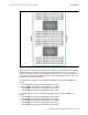
The Figure 2-12 shows the back view diagram of the server with the respective slot numbers.
Figure 2-12 Back view diagram for Power S822
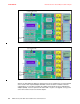
On Figure 2-13 on page 42 and Figure 2-14 on page 42 there are two top view diagrams
showing the available PCIe slots on the two socket server considering both backplane
options. The quantity of disk slots can vary depending on the storage backplane selected. For
more details see2.6, “Internal storage” on page 51.
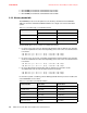
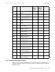
Slot 5 PCIe Gen3 x16 P1-C7 Low profile 1
Slot 6
a
PCIe Gen3 x8 P1-C9 Low profile 1
Slot 7
b
PCIe Gen3 x8 P1-C10 Low profile 1
Slot 8 PCIe Gen3 x8 P1-C11 Low profile 1
Slot 9 PCIe Gen3 x8 P1-C12 Low profile 1
a. Slot 6 (P1-C9) becomes obstructed by external SAS Ports and cannot be used by PCIe devices
when #EJ0U is present. If a PCIe adapter is plugged into slot 6, then #EJ0U cannot be used or
adapter must be moved to another suitable slot.
b. Included on all base configurations this slot (P1-C10) comes populated with a ethernet adapter
PCIe2 LP 4-port 1 Gb Ethernet Adapter (#5260).
Slot Description Location code Card size Installed processors
required to enable