
Owner's manual


522 Chapter 16 Testing EDID
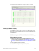
4. Capture the EDID from the connected display device by entering the following
command:
EDA<port>:GDID
Where
port
is the HDMI output port (1 or 2) that the display is connected to. For
example, the command below loads an EDID from a display device connected to the
882’s HDMI Out port 1.
EDA1:GDID
Note: The EDAport:GDID is a command that is new with Release 2.3.0.
5. Store the captured EDID in the 882’s internal file system by entering the following
command:
DIDA filename
Where
filename
is the name of a file in the default directory identified by DIDP. For
example, the command below store an EDID to the default EDID path.
DIDA myedid1
If you want to store the EDID file in a location that is not the default path, you can either
list the path explicitely on the DIDA command line or change the EDID path with DIDP.
For example, the command below loads an EDID from a different directory in
flashmem.
DIDA /tffs0/library/userdata/myedid1
6. (Optional) Use the captured EDID to emulate the display device on the analyzer by
entering the following command:
EDE<port>:DIDU
Where
port
is the HDMI input (Rx) port (1 or 2) that you want to configure to emulate
the EDID. For example, the command below loads the EDID stored in the EDID edit
buffer for emulation into the HDMI input (Rx) port 2.
EDE2:DIDU
Creating or editing EDID contents
You can create or modify an EDID structure to emulate a specific display device using one
of the following methods:
• Using the EDID Editor tool. See “Using the EDID Editor tool” on page 547 for details on
using the EDID Editor tool
• Loading EDID into memory buffer and creating/modifying content using EDID editing
commands. See following procedure for details.