Q6 Edge VA QUANTUM Q6 Edge VA Product Serial #
SAFETY GUIDELINES WARNING! A Quantum Rehab Provider or a qualified technician must perform the initial setup of this power chair and must perform all of the procedures in this manual. The symbols below are used throughout this owner’s manual and on the power chair to identify warnings and important information. It is very important for you to read them and understand them completely. WARNING! Indicates a potentially hazardous condition/situation.
CONTENTS I. INTRODUCTION ...................................................................................................................................4 II. SAFETY .....................................................................................................................................................5 III. YOUR POWER CHAIR ........................................................................................................................7 IV. ASSEMBLY ...............................
I. INTRODUCTION SAFETY WELCOME to Quantum Rehab, a division of Pride Mobility Products (Pride). The power chair you have purchased combines state-of-the-art components with safety, comfort, and styling in mind. We are confident that these design features will provide you with the conveniences you expect during your daily activities. Once you understand how to safely operate and care for your power chair, it should give you years of trouble free operation and service.
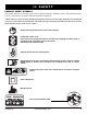
II. SAFETY PRODUCT SAFETY SYMBOLS The symbols below are used on the power chair to identify warnings, mandatory actions, and prohibited actions. It is very important for you to read and understand them completely. NOTE: There are more warnings identified and explained in the Consumer Safety Guide that is included with your power chair. Please become familiar with all the warnings and safety information found in the Consumer Safety Guide and refer to this resource often.
II. SAFETY GENERAL GUIDELINES MANDATORY! Do not operate your new power chair for the first time without completely reading and understanding this owner’s manual. Your power chair is a state-of-the-art life-enhancement device designed to increase mobility. Pride provides an extensive variety of products to best fit the individual needs of the power chair user.
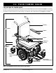
III. YOUR POWER CHAIR THE Q6 EDGE VA POWER CHAIR Your power chair has two main assemblies: the seat assembly and the power base assembly. See figure 1. Typically, the seat assembly includes the armrests, seatback, and seat base. The power base assembly includes two motor/brake assemblies, two drive wheels, four caster wheels, two batteries, and wiring harnesses. See figures 1, 2, and 3.
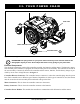
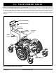
III. YOUR POWER CHAIR REAR SHROUD TRAPEZE BARS FRONT COVER MANUAL FREEWHEEL LEVER SUSPENSION SPRING Figure 2. The Q6 Edge VA Power Base PROHIBITED! The spring tension on your power chair was factory set to meet the needs of the demographic majority of users. Do not adjust the tension of any spring on your power chair. Electrical Components The electrical components consist of the controller assembly, the batteries, and the motors.
III. YOUR POWER CHAIR Main Circuit Breaker (located on the rear main frame): The main circuit breaker is a safety feature built into your power chair. When the batteries and the motors are heavily strained (e.g., from excessive loads), the main circuit breaker trips to prevent damage to the motors and the electronics. If the circuit trips, allow your power chair to “rest” for approximately one minute. Next, push in the circuit breaker button, turn on the controller, and continue normal operation.
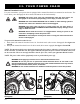
III. YOUR POWER CHAIR Manual Freewheel Levers For your convenience, your power chair is equipped with a manual freewheel lever mounted on each motor. The levers allow you to disengage the drive motors and maneuver the chair manually. WARNING! The power chair could roll unintentionally when the drive motors are disengaged on an incline! Property damage, severe injury or death can occur.
III. YOUR POWER CHAIR MANUAL FREEWHEEL LEVER Figure 5A. Drive Mode (Left Drive Motor Engaged) Q6 Edge VA MANUAL FREEWHEEL LEVER Figure 5B. Drive Mode (Right Drive Motor Engaged) www.pridemobility.
IV. ASSEMBLY INITIAL ASSEMBLY Your power chair may require some assembly either before initial use or after transportation. It may also require disassembly to make some comfort adjustments. Figure 6 details those parts of the power chair that are designed to be disassembled and assembled by an end user or by a qualified caregiver before using the product or making comfort adjustments.
IV. ASSEMBLY Seat Installation It may be necessary to install the seat either prior to initial operation or after transporting your power chair. SEAT LATCH SAFETY For unoccupied transit power chairs, contour seats are attached to the power base with the Universal Mounting System (UMS). The UMS consists of universal parts that may be attached to the seat, regardless of seat width or seat depth. The two main components are aluminum extrusions mounted to the seat base.
IV. ASSEMBLY MANDATORY! Prevent controller harness damage! Avoid routing the controller harness on the outside of the armrest pad. Route the harness under the armrest or toward the inside of the armrest pad. Use correct tiedown points for controller harness to prevent the harness from getting caught in the drive tires, pinched in the seat frame, or damaged when passing through doorways. 5. Plug the controller connector into the rear of the power base. See figure 3. 6.
IV. ASSEMBLY Power Elevating Seat Option Your power chair may be equipped with a power elevating seat option. While the seat itself may be any one of the styles offered for this model, the way the seat base attaches to the power base is different. To install the power elevating seat: l. Place the seat plate interface bracket onto the actuator. See figure 11. 2. Insert the supplied hardware into the actuator and tighten the hardware. 3. Place the seating system onto the seat plate and secure. 4.
V. COMFORT ADJUSTMENTS COMFORT ADJUSTMENTS After becoming familiar with your power chair’s operation, you may find the need to make some adjustments to increase your comfort, such as seat height and angle, armrest width, armrest angle and height, foot platform height, depth, and angle, and controller position. NOTE: If your power chair is equipped with a Specialty Seat, Synergy Seat, or TRU-Balance Power Positioning System, refer to the seat adjustment information contained in separate manuals.
V. COMFORT ADJUSTMENTS 7. Remove the hardware that attaches the trapeze bars to the seat interface weldments. See figure 13. 8. Move the trapeze bars up or down to the desired height. NOTE: Change the seat dump by raising or lowering only one trapeze bar (front or rear). 9. Reinstall the hardware. 10. Reinstall the seat. 11. Reconnect the controller to the power base. Seat Position You can move the seat forward or rearward by changing the extrusion mounting position. To change the position: 1.
V. COMFORT ADJUSTMENTS Seatback Angle Adjustment If your power chair is equipped with an adjustable seatback, you can adjust it to four (4) different angles: 90°, 102°, 105°, or 107°. To adjust the seatback angle: 1. Remove the adjusting screws from each seat hinge. See figure 15. 2. Set the seatback at the desired angle. 3. Reinstall the adjusting screws to each seat hinge and tighten. Armrest Width Adjustment You can change each armrest’s width independently of the other.
V. COMFORT ADJUSTMENTS Controller Position You can move the controller in toward or out away from the armrest, or change the position of the controller for either left-hand or right-hand use. WARNING! Do not place the controller harness so that it can be pinched in the seat frame or the power base frame. CONTROLLER BRACKET To extend the controller: 1. Flip up the armrest so it is perpendicular to the floor. 2. Loosen the setscrew on the controller bracket. See figure 16. 3.
V. COMFORT ADJUSTMENTS Foot Platform Height Adjustment The foot platform height is easily adjusted to several different heights. To raise or lower the foot platform: 1. Remove the hardware from the foot platform bracket. See figure 17. 2. Raise or lower the foot platform to the desired height. 3. Reinstall the hardware into the foot platform bracket and tighten. Foot Platform Depth Adjustment You can adjust the depth of the foot platform. To adjust the foot platform depth: 1.
V. COMFORT ADJUSTMENTS Power Elevating Seat (Optional) If your power chair is equipped with a power elevating seat, you can change the seat height either through the controller or through a toggle switch mounted to one of the armrests. To change the seat height through toggle switch: 1. Press forward on the toggle switch to raise the seat. See figure 18. 2. Pull back on the toggle switch to lower the seat.
V. COMFORT ADJUSTMENTS Positioning Belt Your power chair may be equipped with a positioning belt that can be adjusted for operator comfort. See figure 19. The positioning belt is designed to support the operator so that he/she does not slide down or forward in the seat. The positioning belt is not designed for use as a restraining device. WARNING! The positioning belt is not designed for use as a seat belt in a motor vehicle. Nor is your power chair suitable for use as a seat in any vehicle.
VI. BATTERIES AND CHARGING BATTERIES AND CHARGING The Q6 Edge VA uses two long-lasting, 12-volt, deep-cycle batteries. These batteries are sealed and maintenance free. Since they are sealed, there is no need to check the electrolyte (fluid) level. Deep-cycle batteries are designed to handle a longer and deeper discharge. Though they are similar in appearance to automotive batteries, they are not interchangeable.
VI. BATTERIES AND CHARGING To charge the batteries using the off-board charger: 1. Position your power chair next to a standard electrical outlet. 2. Be certain the controller power is turned off and the power chair is in drive mode. 3. Plug the off-board charger into the off-board charger/ programming socket on the controller. See figure 20. 4. Plug the off-board charger into the electrical outlet.
VI. BATTERIES AND CHARGING Daily Use If you use your power chair on a daily basis, charge the batteries as soon as you are finished using your power chair. Your power chair will be ready each morning to give you a full day’s service. It is recommended that you charge the batteries at least 8 to 14 hours after daily use. Pride recommends that you charge the batteries for an additional 4 hours after the battery charger indicates that charging is complete.
VI. BATTERIES AND CHARGING How can I ensure maximum battery life? A fully charged deep-cycle battery will provide reliable performance and extended battery life. Keep your power chair’s batteries fully charged whenever possible. Batteries that are regularly and deeply discharged, infrequently charged, or stored without a full charge may be permanently damaged, causing unreliable power chair operation and limited battery life.
VII. CARE AND MAINTENANCE CARE AND MAINTENANCE Your Q6 Edge VA is a sophisticated power chair. Like any motorized vehicle, it requires routine maintenance checks. You can perform some of these checks, but others require assistance from your Quantum Rehab Provider. Preventive maintenance is very important. If you follow the maintenance checks in this section as scheduled, you can help ensure that your power chair gives you years of trouble-free operation.
VII. CARE AND MAINTENANCE The body shroud has been sprayed with a clear sealant coating. You can apply a light coat of car wax to help it retain its high-gloss appearance. Check all electrical connections. Make sure they are tight and are not corroded. Batteries must sit flat within the battery tray, with the battery terminals facing rearward. Refer to the battery wiring label for the correct wiring layout.
VII. CARE AND MAINTENANCE Storage Your power chair should be stored in a dry place, free from temperature extremes. When storing, disconnect the batteries from the power chair. See VI. “Batteries and Charging.” WARNING! If you fail to store the unit properly, the frame can rust and the electronics can be damaged. Any corroded electronic connection should be replaced.
VII. CARE AND MAINTENANCE TIRE TUBE WHEEL HUB SCREWS FRONT RIM HALF REAR RIM HALF LUG NUTS Figure 21. Q6 Edge VA Drive Wheel Figure 22. Q6 Edge VA Drive Wheel Disassembled Follow these easy steps for a quick and safe repair for both pneumatic and solid tires: 1. Turn off the power to the controller. 2. Set the power chair up on blocks. 3. If you are changing a pneumatic tire, completely deflate it before removing the wheel. 4. Remove the (5) lug nuts from the wheel hub. See figure 21. 5.
VII. CARE AND MAINTENANCE To replace the batteries: 1. Turn off the power to the controller. 2. Make sure that the power chair is in drive mode. See III. “Your Power Chair.” 3. Remove the front cover by squeezing the release handles (see figure 23) and lifting the foot platform bracket up and away from the power base. 4. Disconnect the quick release battery connectors. See figure 23. 5. Remove the batteries. 6. Disconnect the battery harness from each battery. 7.
VII. CARE AND MAINTENANCE When to See Your Quantum Rehab Provider for Service The following symptoms could indicate a serious problem with your power chair. If necessary, contact your Quantum Rehab Provider. When calling, have the model number, serial number, nature of the problem, and the error code if available.
NOTES Q6 Edge VA www.pridemobility.
NOTES 34 www.pridemobility.
SAFETY GUIDELINES WARNING! A Quantum Rehab Provider or a qualified technician must perform the initial setup of this power chair and must perform all of the procedures in this manual. The symbols below are used throughout this owner’s manual and on the power chair to identify warnings and important information. It is very important for you to read them and understand them completely. WARNING! Indicates a potentially hazardous condition/situation.
Q6 Edge VA QUANTUM Q6 Edge VA Product Serial #