Owner’s Manual 1-800-800-8586 (Exeter, PA) • 1-888-570-1113 (St. Catharines, ON) • www.quantumrehab.
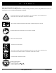
SAFETY GUIDELINES The symbols below are used throughout this owner's manual and on the power chair to identify warnings and important information. It is very important for you to read them and understand them completely. WARNING! Failure to follow designated procedures can cause either personal injury, component damage, or malfunction (black symbol on yellow triangle with black border). MANDATORY! These actions should be performed as specified.
CONTENTS I. INTRODUCTION..................................................................................................................................... 4 II. SAFETY ..................................................................................................................................................... 6 III. YOUR POWER CHAIR ........................................................................................................................ 16 IV. ASSEMBLY/DISASSEMBLY .............
I. INTRODUCTION SAFETY WELCOME to Quantum Rehab, a division of Pride Mobility Products Corporation (Pride). The power chair you have purchased combines state-of-the-art components with safety, comfort, and styling in mind. We are confident that these design features will provide you with the conveniences you expect during your daily activities. Once you understand how to safely operate and care for your power chair, it should give you years of trouble free operation and service.
I. INTRODUCTION PRIDE OWNERS CLUB As an owner of a Pride product, you are invited to register your product's warranty and enroll in the Pride Owners Club. You may do so by filling out and returning your enclosed product registration card or by visiting Pride's web site at www.pridemobility.com. As a registered member, each time you visit our site, you will have access to the most interactive and honest educational venue available today for people with mobility needs, their families, and friends.
II. SAFETY PRODUCT SAFETY SYMBOLS The symbols below are used on the power chair to identify warnings, mandatory actions, and prohibited actions. It is very important for you to read and understand them completely. Corrosive chemicals contained in battery. Use only AGM or Gel-Cell batteries to reduce the risk of leakage or explosive conditions. This product has been tested and passed at an immunity level of 20 V/m. Read and follow the information in the owner’s manual. Maximum seating weight.
II. SAFETY Do not remove anti-tip wheels. Do not use a cell phone, walkie/talkie, laptop, or other radio transmitter while operating. Avoid exposure to rain, snow, ice, salt, or standing water whenever possible. Maintain and store in a clean and dry condition. Removal of grounding prong can create electrical hazard. If necessary, properly install an approved 3-pronged adapter to an electrical outlet having 2-pronged plug access. Failure to heed could result in personal injury and/or property damage.
II. SAFETY SAFETY MANDATORY! Do not operate your new power chair for the first time without completely reading and understanding this owner’s manual. Your power chair is a state-of-the-art life-enhancement device designed to increase mobility. Pride provides an extensive variety of products to best fit the individual needs of the power chair user.
II. SAFETY Weight Limitations Your power chair is rated for a maximum weight capacity. Please refer to the specifications table for this limit. WARNING! Exceeding the weight capacity voids your warranty and may result in personal injury and/or damage to your power chair. Pride will not be held responsible for injuries and/or property damage resulting from failure to observe weight limitations. WARNING! Do not carry passengers on your power chair.
II. SAFETY WARNING! Even though your power chair is capable of climbing slopes greater than those illustrated in figure 1, do not, under any circumstances, exceed the incline guidelines or any other specifications presented in this manual. Doing so could cause instability in your power chair, resulting in personal injury and/ or damage to your power chair. In compliance with the Americans with Disabilities Act of 1990, all handicap public access ramps are required to have a maximum slope of 5° (8.7%).
II. SAFETY Freewheel Mode Your power chair is equipped with a manual freewheel system to allow for manual maneuverability by a trained attendant. For more information about how to place your power chair into and out of freewheel mode, see III. “Your Power Chair.” WARNING! Do not use your power chair in freewheel mode without an attendant present. Personal injury may result. WARNING! Do not attempt to personally place your power chair in freewheel mode while seated on it. Personal injury may result.
II. SAFETY Transfers Transferring onto and off of your power chair requires a good sense of balance. Always have an attendant or healthcare professional present while learning to properly transfer yourself. To eliminate the possibility of injury, Pride recommends that you or a trained attendant perform the following tasks before attempting a transfer: ! Turn off power to the controller. See VII. “Operation.” ! Ensure your power chair is not in freewheel mode. See III. “Your Power Chair.
II. SAFETY Elevators Modern elevators have a door edge safety mechanism that, when pushed, reopens the elevator door(s). ! If you are in the doorway of an elevator when the door(s) begin to close, push on the rubber door edge or allow the rubber door edge to contact the power chair and the door will reopen. ! Use care that pocketbooks, packages, or power chair accessories do not become caught in elevator doors.
II. SAFETY Preventing Unintended Movement WARNING! If you anticipate being seated in a stationary position for an extended period of time, turn off the power. This will prevent unexpected motion from inadvertent joystick contact. This will also eliminate the possibility of unintended chair movement from electromagnetic (EM) sources. Failure to do so may result in personal injury. Removable Parts WARNING! Do not attempt to lift or move a power chair by any of its removable parts.
II. SAFETY Electromagnetic and Radio Frequency Interference (EMI/RFI) WARNING! Laboratory tests have shown that electromagnetic and radio frequency waves can have an adverse affect on the performance of electrically-powered mobility vehicles.
I I I . YO U R P OW E R C H A I R THE QUANTUM 1107 The Quantum 1107 has two main assemblies: the seat assembly and the power base assembly. See figure 5. Typically, the seat assembly includes the armrests, seatback, and seat base. The power base assembly includes two motor/brake assemblies, two drive wheels, two anti-tip wheels, two caster wheels, two battery boxes, and wiring harnesses. See figure 5, 6, and 7.
I I I . YO U R P OW E R C H A I R QUANTUM 1107 SPECIFICATIONS Suspension: Active-Trac Drive Wheels: 10 in., pneumatic, (10 in., solid are optional) Caster Wheels: 6 in., solid, rear-mounted Anti-tip Wheels: 5 in., solid, front-mounted Maximum Speed:¹ Up to 4.5 mph Brakes: “Intelligent Braking” electronic regenerative, disc park brake Ground Clearance:² 2.5 in. Maximum Safe Slope: 5° (8.7%) Turning Radius:² 20.5 in. (without foot riggings) Overall Size:² Length: 36.625 in.
I I I . YO U R P OW E R C H A I R SIDE FRAME HANDLES BATTERY BOXES FRONT TRAPEZE BAR CONTROLLER CABLE CONNECTOR MANUAL FREEWHEEL LEVER MOTOR/BRAKE ASSEMBLY Figure 6. The Quantum 1107 Power Base 18 www.quantumrehab.
I I I . YO U R P OW E R C H A I R Electrical Components The electrical components consist of the controller assembly, the batteries, and the motors. The batteries, motors, and controller power module (if equipped) are located on the power base assembly. See figures 6 and 7. The controller is located on the seat assembly. Connectivity between the controller and the motors, the batteries, and the battery charger is provided by one or more wiring harnesses.
I I I . YO U R P OW E R C H A I R Main Circuit Breaker (located on rear battery box): The main circuit breaker is a safety feature built into your power chair. When the batteries and the motors are heavily strained (e.g., from excessive loads), the main circuit breaker trips to prevent damage to the motors and the electronics. If the circuit trips, allow your power chair to “rest” for approximately one minute.
I V. ASSEMBLY/DISASSEMBLY INITIAL ASSEMBLY Your power chair may require some assembly either before initial use or after transportation. It may also require disassembly to make some comfort adjustments. Figure 10 details those parts of the power chair that are designed to be disassembled and assembled by an end user or by a qualified caregiver before using the product or making comfort adjustments.
I V. ASSEMBLY/DISASSEMBLY Seat Installation The Quantum 1107 use a seat interface system to attach the seat assembly to the power base assembly. This enables you to install and remove the seat quickly and easily. The main components are a pair of aluminum extrusions mounted to the underside of the seat base and seat interface mounted on the power base. See figures 11 and 12. WARNING! Avoid injury! Do not pick up the seat assembly by the armrests.
I V. ASSEMBLY/DISASSEMBLY Power Base Disassembly The Quantum 1107 power base disassembles into six parts for easy transportation and storage. See figure 13. To disassemble the power chair: 1. Turn off the power to the controller. 2. Disconnect the controller. See figure 6. 3. Remove the seat. 4. Press the foot platform release button and lift off the foot platform. See figure 13. 5. Flip down the battery box latches on each side of the power base. See figure 14. 6.
I V. CENTER SECTION LATCH ASSEMBLY/DISASSEMBLY BATTERY BOX LATCH (UNLOCKED) BATTERY BOX LATCH (LOCKED) Figure 14. Quantum 1107 Battery Box Removal and Frame Separation 24 www.quantumrehab.
V. COMFORT ADJUSTMENTS COMFORT ADJUSTMENTS After becoming familiar with your power chair’s operation, you may find the need to make some adjustments to increase your comfort. These adjustments include seat height and angle, armrest angle, foot platform height and angle, and controller position. If your power chair is equipped with a Specialty Seat or a Synergy Seat, refer to the information provided in separate manuals.
V. COMFORT ADJUSTMENTS 10. Reinstall the seat. 11. Reconnect the controller to the power base. Seat Position You can move the seat forward or rearward by changing the extrusion mounting position. To change the position: 1. Turn off the power to the controller. 2. Unplug the controller from the power base. 3. Remove the seat from the power base. 4. Remove both extrusions from the bottom of the seat. See figure 17. 5. Reposition the extrusions on a different set of mounting holes.
V. COMFORT ADJUSTMENTS To change the armrest width: 1. Locate the armrest knob on each side of the armrest receiver bracket. See figure 18. 2. Loosen each knob. 3. Slide the armrests in or out to the desired width. 4. Tighten each knob. SETSCREW Armrest Angle Adjustment To change the armrest angle: 1. Lift the armrest straight up so that it is perpendicular to the floor. See figure 18. 2. Loosen the jam nuts. 3.
V. COMFORT ADJUSTMENTS Foot Platform Height Adjustment The foot platform height is easily adjusted to different heights in 1/2-in. increments. NUT BOLT CAM To raise or lower the foot platform: 1. Remove the quick release fasteners from the foot platform bracket. See figure 21. 2. Raise or lower the foot platform to the desired height. 3. Reinstall the quick release fasteners into the foot platform bracket and tighten. Foot Platform Depth Adjustment To adjust the foot platform depth: 1.
V. COMFORT ADJUSTMENTS Swing-away Footrests Swing-away Footrests (SFRs) enable you to rotate the footrests to the side before you transfer onto or off of your power chair. RELEASE LEVER A RELEASE LEVER B To rotate the SFRs: 1. Push in the release lever. See figure 24. 2. Rotate the SFRs. LEG REST EXTENSION LEG REST ADJUSTMENT SCREWS To adjust the SFR length: 1. Remove the two adjustment screws from the side of each footrest extension. See figure 24. 2.
V. COMFORT ADJUSTMENTS To change foot plate position (B): 1. Remove the hardware. 2. Move the foot plate to the desired position. 3. Reinstall the hardware. BOLT B To change foot plate tilt (C): 1. Loosen the hardware. 2. Tilt the foot plate to desired position. 3. Tighten the hardware. NUT A To change foot plate angle (D): 1. Turn the setscrew clockwise to decrease the angle. 2. Turn the setscrew counterclockwise to increase the angle.
VI. BATTERIES AND CHARGING BATTERIES AND CHARGING Your power chair uses two long-lasting, 12-volt, deep-cycle batteries. These batteries are sealed and maintenance free. Since they are sealed, there is no need to check the electrolyte (fluid) level. Deep-cycle batteries are designed to handle a longer and deeper discharge. Though they are similar in appearance to automotive batteries, they are not interchangeable.
VI. BATTERIES AND CHARGING To charge the batteries using the off-board charger: 1. Position your power chair next to a standard electrical outlet. 2. Be certain the controller power is turned off. 3. Plug the off-board charger into the off-board charger/programming socket on the controller. See VII. “Operation.” 4. Plug the off-board charger into the electrical outlet. NOTE: If it is a Pride off-board charger, then there are two lights in it.
VI. BATTERIES AND CHARGING Can I use a different battery charger? You should use the charger supplied with the power chair. It is the safest, most efficient tool to charge the batteries. We do not recommend using other types of chargers (e.g., an automotive battery charger). NOTE: Your power chair’s charger will not operate after the batteries have been discharged to nearly zero voltage. If this happens, call your Quantum Rehab Specialist for assistance.
VI. BATTERIES AND CHARGING We work closely with our battery manufacturer to provide a battery that best suits your power chair’s specific demands. Fresh batteries arrive regularly at Pride and are promptly shipped with a full charge. During shipping, the batteries encounter temperature extremes that may influence initial performance. Heat robs the charge from the battery, and cold slows the power available and extends the time needed to recharge the battery (just as with a car battery).
VII. OPERATION FLIGHT CONTROLLER The electronic controller is what you use to operate your power chair. It takes the battery voltage and sends it to the appropriate system. The electronic controller enables you to move the power chair, as well as monitor battery charge, electronic controller functions, and the condition of your electrical system. The FLIGHT is part of a modular electronic controller system. The system consists of more than one module.
VII. OPERATION On/Off Key The on/off key turns the FLIGHT on and off. BATTERY CONDITION METER WARNING! Unless faced with an emergency situation, do not use the on/off key to stop the chair. This will cause the power chair to stop abruptly. WARNING! Always turn the power off when you are stationary to prevent unexpected movement.
VII. OPERATION Horn Key The horn key activates the horn. Speed Keys There are two keys that control the speed. Press the hare key to increase the speed. Press the tortoise key to decrease the speed. The speed setting is displayed on the speed setting indicator. If your power chair was programmed with a drive profile, contact your Quantum Rehab Specialist for more information.
VII. OPERATION VSI ELECTRONIC CONTROLLER The electronic controller is what you use to operate your power chair. The electronic controller enables you to move the power chair, as well as monitor battery charge, electronic controller functions, and the condition of your electrical system. The VSI electronic controller is an integral electronic controller. All of the electronics necessary to operate the power chair are contained in one module. See figure 31.
VII. OPERATION On/Off Key The on/off key turns the VSI on and off. WARNING! Unless faced with an emergency situation, do not use the on/off key to stop the power chair. This will cause the power chair to stop abruptly. WARNING! Always turn the power off when you are stationary to prevent unexpected movement. Battery Condition Meter The battery condition meter is a 10-segment illuminated display located in front of the joystick. It consists of red, yellow, and green lights.
VII. OPERATION Actuator Keys and Actuator Lights (For Optional Equipment) Actuator keys and actuator lights are used for optional equipment such as power elevating leg rests. For specific operation of the actuator keys and actuator lights, contact your Quantum Rehab Specialist. Horn Key The horn key activates the horn. Locking/Unlocking the VSI The VSI has a feature that enables you to lock your power chair to prevent unauthorized use. To lock the VSI: 1.
VII. OPERATION Thermal Rollback The VSI controller is equipped with a thermal rollback circuit. This circuit monitors the temperature of the controller, which roughly translates to motor temperature. In the event that the VSI controller becomes excessively hot (above 140° F), motor current (amperage) is reduced. For every degree above 140° F, the motor current limit is reduced by .55 amps until the VSI controller reaches 158° F, at which time the current output is reduced to zero.
VII. OPERATION REMOTE PLUS CONTROLLER The electronic controller is what you use to operate your power chair. The electronic controller enables you to move the power chair, as well as monitor battery charge, electronic controller functions, and the condition of your electrical system. The Remote Plus is part of a modular electronic controller system. The system consists of more than one module. Typically, the Remote Plus is mounted to one of the armrests. See figure 33.
VII. OPERATION Mode Key (Speed Settings) The mode key controls the speed settings. The Remote Plus speed settings range from 1 to 5. Typically, the slowest speed setting is 1 and the fastest speed setting is 5. The settings are indicated by the number of lights that are lit on the speed setting indicator. NOTE: The speed settings are preset at the factory. If your Quantum Rehab Specialist changes the order of these settings, please make note of these changes.
VII. OPERATION NOTE: When the batteries approach a discharged state, the first red light will begin to slowly flash, reminding you the batteries need to be charged immediately! Right/Left Turn Indicator Keys (Optional) The right/left turn indicator keys toggle either the left or right turn indicators. Press once to turn on and press again to turn off. You can also turn off the selected turn indicator by pressing the opposite indicator key or the hazard key.
VII. OPERATION Remote Plus Error Codes In addition to indicating the current state of battery charge, the battery condition meter can also indicate possible problems with your power chair’s electrical system. If any of the battery condition meter lights are flashing rapidly, the controller may be indicating an error. Error codes are displayed as a number of flashing lights. For instance, if the first light is flashing rapidly, the battery voltage is nearly depleted.
VII. OPERATION THE MICRODRIVE CONTROLLER The electronic controller is what you use to operate your power chair. It takes the battery voltage and sends it to the appropriate system. The electronic controller also enables you to monitor battery charge, electronic controller functions, and the condition of your electrical system. Also, it may be used to control some optional systems such as power elevating seats and lights. The Microdrive electronic control system is a modular system.
VII. OPERATION Display Pad The display pad is located directly in front of the joystick. It contains the horn key, battery condition meter, profile and speed indicator, and the actuator indicator. See figure 36. Horn Key The horn key activates the horn. Battery Condition Meter The battery condition meter is a 10-segment illuminated display that indicates that the Microdrive is powered on and also gives the status of the batteries, the controller, and the power chair electrical system.
VII. OPERATION Drive Profile Selection Your Microdrive controller may be programmed for more than one drive profile that allows the system to be custom tailored to your environment. To select a profile setting: 1. Use the on/off switch to power on the chair and the controller. 2. Press the mode button. 3. Move the joystick left or right to select the desired drive profile. Each of the LEDs indicate a separate profile. NOTE: The system can be programmed with 5 different profiles.
VII. FLASHING LIGHTS OPERATION DIAGNOSIS SOLUTION 10 High Battery Voltage Check batteries. 9 Solenoid Brake Fault Check motor/brake wiring. 8 Possible Controller Fault See Quantum Rehab Specialist. 7 Possible Joystick Fault See Quantum Rehab Specialist. 6 Inhibit Active Unplug charger. Check connections. 5 Right Motor Wiring Fault Check right motor wiring. 4 Right Motor Disconnected Check right motor wiring. 3 Left Motor Wiring Fault Check left motor wiring.
VIII. CARE AND MAINTENANCE CARE AND MAINTENANCE Your power chair is a sophisticated device. Like any motorized vehicle, it requires routine maintenance checks. You can perform some of these checks, but others require assistance from your Quantum Rehab Specialist. Preventive maintenance is very important. If you follow the maintenance checks in this section as scheduled, you can help ensure that your power chair gives you years of trouble-free operation.
VIII. CARE AND MAINTENANCE ! The body shroud has been sprayed with a clear sealant coating. You can apply a light coat of car wax to help it retain its high-gloss appearance. ! Check all electrical connections. Make sure they are tight and are not corroded. ! All wheel bearings are prelubricated and sealed. They require no subsequent lubrication. Daily Checks ! With the controller turned off, check the joystick.
VIII. CARE AND MAINTENANCE WARNING! If you fail to store the unit properly, the frame can rust and the electronics can be damaged. Disposal of Your Power Chair Your power chair must be disposed of according to applicable local and national statutory regulations. Contact your local waste disposal agency or Quantum Rehab Specialist for information on proper disposal of power chair packaging, metal frame components, plastic components, electronics, and batteries.
VIII. CARE AND MAINTENANCE Follow these easy steps for a quick and safe repair for both pneumatic and solid tires: 1. Turn off the power to the controller. 2. Set the power chair up on blocks. 3. If you are changing a pneumatic tire, completely deflate it before removing the wheel. 4. Remove the drive wheel nut and washer from the axle. See figure 37. 5. Pull the wheel off the axle. 6. Remove the nuts and washers from the wheel hub and separate the rim halves. See figure 38. 7.
VIII. CARE AND MAINTENANCE 7. Reconnect the battery harnesses according to the battery wiring diagram label. See figure 40. WARNING! Prevent injury. Make sure you tighten the fasteners so that the connections are secure. 8. Reinstall the battery boxes onto the power base. Make sure that the battery box latches are in the up (locked) Figure 40. Battery Wiring Diagram Label position. 9. Charge the batteries. See VI. “Batteries and Charging.
IX.
IX. WARRANTY RECONDITIONED UNITS WARRANTY All reconditioned units are covered by a six-month warranty from Pride effective from the date of purchase. WARRANTY EXCLUSIONS This warranty does not extend to those items which may require replacement due to normal wear and tear.
NOTES Quantum 1107 www.quantumrehab.
NOTES 58 www.quantumrehab.
Thank you for making the Quantum 1107 your choice in power chairs. Q u a l i t -yQuantum C o n t r o l 1107 - M o d e l 1 400 Quality Control Inclusion of all Parts Fit and Finish Joystick Serial Number Performance Controller Serial Number Left Motor Serial Number We have thoroughly inspected your Quantum 1107. The following check marks indicate that it has been tested, driven, and inspected. Right Motor Serial Number # In Q 1 uali ty Pride keeps a more detailed report on file at the factory.