Quality Control – Quantum 1121 Series Inclusion of all Parts QUANTUM SERIES Joystick Serial Number Controller Serial Number Left Motor Serial Number Right Motor Serial Number Fit and Finish Performance Pride keeps a more detailed report on file at the factory.
SAFETY GUIDELINES WARNING! A Quantum Rehab Provider or a qualified technician must perform the initial setup of this power chair and must perform all of the procedures in this manual. The symbols below are used throughout this owner’s manual and on the power chair to identify warnings and important information. It is very important for you to read them and understand them completely. WARNING! Indicates a potentially hazardous condition/situation.
CONTENTS I. INTRODUCTION ................................................................................................................................... 4 II. SAFETY .................................................................................................................................................... 5 III. YOUR POWER CHAIR ...................................................................................................................... 15 IV. ASSEMBLY ..............................
I. INTRODUCTION SAFETY WELCOME to Quantum Rehab, a division of Pride Mobility Products (Pride). The power chair you have purchased combines state-of-the-art components with safety, comfort, and styling in mind. We are confident that these design features will provide you with the conveniences you expect during your daily activities. Once you understand how to safely operate and care for your power chair, it should give you years of trouble free operation and service.
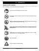
II. SAFETY PRODUCT SAFETY SYMBOLS The symbols below are used on your power chair to identify warnings, mandatory actions, and prohibited actions. It is very important for you to read and understand them completely. Read and follow the information in the owner’s manual. Do not allow unsupervised children to play near the power chair while the batteries are charging. Keep your hands away from the tires when driving. Be aware that loose fitting clothing can become caught in the drive tires.
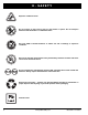
II. SAFETY Explosive conditions exist! Do not expose to heat source such as open flame or sparks. Do not transport batteries with flammable or combustible items. Use only AGM or Gel-Cell batteries to reduce the risk of leakage or explosive conditions. Keep tools and other metal objects away from battery terminals. Contact with tools can cause an electrical shock. Do not use batteries with different amp-hour (Ah) capacities. Do not mix old and new batteries.
II. SAFETY GENERAL GUIDELINES MANDATORY! Do not operate your new power chair for the first time without completely reading and understanding this owner’s manual. Your power chair is a state-of-the-art life-enhancement device designed to increase mobility. Pride provides an extensive variety of products to best fit the individual needs of the power chair user.
II. SAFETY Weight Limitations Your power chair is rated for a maximum weight capacity. Please refer to the specifications table for this limit. Keep in mind that the maximum weight capacity includes the combined weight of the user and any accessories mounted to the power chair. WARNING! Stay within the specified weight capacity of your power chair. Exceeding the weight capacity voids your warranty.
II. SAFETY WARNING! If your power chair is equipped with a reclining seatback, do not attempt to negotiate inclines with the seat in a reclined position. Do not attempt to negotiate obstacles with the seat in a reclined position unless an attendant is present to help stabilize the chair. Failure to heed may result in the power chair tipping over.
II. SAFETY Public Streets and Roadways WARNING! You should not operate your power chair on public streets and roadways. Be aware that it may be difficult for traffic to see you when you are seated on your power chair. Obey all local pedestrian traffic rules. Wait until your path is clear of traffic, and then proceed with extreme caution.
II. SAFETY Figure 2. Correct Curb Approach Figure 3. Incorrect Curb Approach Stairs and Escalators Power chairs are not designed to travel up or down stairs or escalators. Always use an elevator. WARNING! Never use your power chair to negotiate steps or escalators. Doors Determine if the door opens toward or away from you. Drive your power chair gently and slowly forward to push the door open. Or drive your power chair gently and slowly backward to pull the door open.
II. SAFETY Positioning Belts Your Quantum Rehab Provider, therapist(s), and other healthcare professionals are responsible for determining your requirement for a positioning belt in order to operate your power chair safely. WARNING! If you require a positioning belt to safely operate your power chair, make sure it is fastened securely in order to reduce the possibility of a fall from the power chair. WARNING! The positioning belt is not designed for use as a seat belt in a motor vehicle.
II. SAFETY Transfers Transferring onto and off of your power chair requires a good sense of balance. Always have an attendant or healthcare professional present while learning to properly transfer yourself. To eliminate the possibility of injury, Pride recommends that you or a trained attendant perform the following tasks before attempting a transfer: Turn off the power to the controller. Ensure your power chair is not in freewheel mode. See III. “Your Power Chair.
II. SAFETY Alcohol/Smoking The power chair user must exercise care and common sense when operating his/her power chair. This includes awareness of safety issues while under the influence of alcohol or while smoking. WARNING! Do not operate your power chair while you are under the influence of alcohol, as this may impair your ability to operate your power chair in a safe manner.
III. YOUR POWER CHAIR THE QUANTUM 1121 SERIES POWER CHAIR Your power chair has two main assemblies: the seat and the power base. See figures 5 and 6. Typically, the seat assembly includes the armrests, seatback, and seat base. The power base assembly includes two motor/brake assemblies, two drive wheels, two anti-tip wheels, two caster wheels, two batteries, and wiring harnesses.
III. YOUR POWER CHAIR ELECTRONICS TRAY REAR SEAT TOWERS FRONT SEAT TOWERS POWER MODULE (LOCATED UNDER ELECTRONICS TRAY) FREEWHEEL LEVER MOTOR/BRAKE ASSEMBLY Figure 6. The Quantum 1121 Series Power Base Electronics Tray The electronics tray is located on the back of the power base. See figure 6. Main Circuit Breaker: The main circuit breaker is a safety feature built into your power chair. When the batteries and the motors are heavily strained (e.g.
III. YOUR POWER CHAIR Manual Freewheel Lever For your convenience, your power chair is equipped with a manual freewheel system. This system consists of one or more freewheel levers which enable you to disengage the drive motors and maneuver the chair manually. WARNING! Do not use your power chair while the drive motors are disengaged! Do not disengage the drive motors when your power chair is on an incline or decline, as the unit could roll on its own. Only engage the freewheel mode when on a level surface.
IV. ASSEMBLY INITIAL ASSEMBLY Your power chair may require some assembly either before initial use or after transportation. It may also require disassembly to make some comfort adjustments. NOTE: Any nylon insert lock nut removed during the disassembly or adjustment of the power chair must be replaced with a new nut. Nylon insert lock nuts should not be reused as it may cause damage to the nylon insert, resulting in a less secure fit.
IV. ASSEMBLY To install the seat: 1. Set the seat towers to the desired height. To change the seat height, see V. “Comfort Adjustments.” 2. Tilt the seat back, and slide the rear extrusion onto the rear trapeze bar. 3. Lower the front extrusion onto the front trapeze bar until the seat latches into place. 4. Flip the seat latch safety down. WARNING! Make sure the seat latch safety is flipped down before using your power chair. 5. Install the controller into one of the armrests. See V. “Comfort Adjustments.
V. COMFORT ADJUSTMENTS COMFORT ADJUSTMENTS After becoming familiar with your power chair’s operation, you may find the need to make some adjustments to increase your comfort, such as seat height and angle, armrest angle, foot platform height and angle, and the controller’s position. NOTE: If your power chair is equipped with a Specialty Seat, Synergy Seat, or Synergy TRU-Balance, refer to the information provided in separate manuals.
V. COMFORT ADJUSTMENTS 9. Reinstall the retaining clip into each seat tower. 10. Reinstall the seat. 11. Plug the controller connector(s) into the electronics tray. NOTE: Make sure the seat latch safety is flipped down before using the power chair seat. Seat Position Adjustment You can move the seat forward or rearward by changing the extrusion mounting position. To change the position: 1. Turn off the power to the controller. 2. Remove the seat. 3. Remove both extrusions from the bottom of the seat.
V. COMFORT ADJUSTMENTS Seatback Angle Adjustment If your power chair is equipped with an adjustable seatback, you can adjust it to four (4) different angles: 90°, 102°, 105°, or 107°. To adjust the seatback angle: 1. Remove the seatback angle adjustment screws on both seat hinges. See figure 16. 2. Set the seatback at the desired angle. 3. Reinstall the screws to both seat hinges and tighten. Armrest Width Adjustment You can change each armrest’s width independently of each other.
V. COMFORT ADJUSTMENTS Controller Position You can move the controller in toward or out away from the armrest, or change the position of the controller for either left-hand or right-hand use. WARNING! Do not place the controller harness so that it can be pinched in the seat frame or the power base frame. CONTROLLER BRACKET SETSCREW To extend the controller: 1. Flip up the armrest so it is perpendicular to the floor. 2. Loosen the setscrew on the controller bracket. See figure 17. 3.
V. COMFORT ADJUSTMENTS Foot Platform Angle Adjustment You can adjust the angle of the foot platform with a hex key. See figure 19. To adjust the foot platform angle: 1. Locate the setscrew on the underside of the foot platform. 2. Turn the setscrew to raise or lower the front of the foot platform. Anti-Tip Wheels The anti-tip wheels are designed to give your power chair increased stability on rough surfaces. The antitip wheels are preset for smooth surfaces or indoor use only.
V. COMFORT ADJUSTMENTS Power Elevating Seat (Optional) If your power chair is equipped with a power elevating seat, you can change the seat height either through the controller or through the toggle switch mounted to one of the armrests. To change the seat height through toggle switch: 1. Press forward on the toggle switch to raise the seat. See figure 21. 2. Pull back on the toggle switch to lower the seat.
VI. BATTERIES AND CHARGING BATTERIES AND CHARGING The power chair uses two long-lasting, 12-volt, deep-cycle batteries. These batteries are sealed and maintenance free. Since they are sealed, there is no need to check the electrolyte (fluid) level. Deep-cycle batteries are designed to handle a longer and deeper discharge. Though they are similar in appearance to automotive batteries, they are not interchangeable.
VI. BATTERIES AND CHARGING To charge the batteries using the off-board charger: 1. Position the front of your power chair next to a standard electrical outlet. See figure 22. 2. Be certain the controller power is turned off and the power chair is in drive mode. 3. Plug the off-board charger into the off-board charger/ programming socket on the controller. 4. Plug the off-board charger into the electrical outlet.
VI. BATTERIES AND CHARGING Daily Use If you use your power chair on a daily basis, charge the batteries as soon as you are finished using your power chair. Your power chair will be ready each morning to give you a full day’s service. It is recommended that you charge the batteries 8 to 14 hours after daily use. Infrequent Use If you use your power chair infrequently (once a week or less), you should charge the batteries at least once per week for 12 to 14 hours.
VI. BATTERIES AND CHARGING How can I ensure maximum battery life? A fully charged deep-cycle battery will provide reliable performance and extended battery life. Keep your power chair’s batteries fully charged whenever possible. Batteries that are regularly and deeply discharged, infrequently charged, or stored without a full charge may be permanently damaged, causing unreliable power chair operation and limited battery life.
VII. CARE AND MAINTENANCE CARE AND MAINTENANCE Your Quantum 1121 is a sophisticated power chair. Like any motorized vehicle, it requires routine maintenance checks. You can perform some of these checks, but others require assistance from a Quantum Rehab Provider. Preventive maintenance is very important. If you follow the maintenance checks in this section as scheduled, you can help ensure that your power chair gives you years of trouble-free operation.
VII. CARE AND MAINTENANCE All wheel bearings are prelubricated and sealed. They require no subsequent lubrication. The body shroud has been sprayed with a clear sealant coating. You can apply a light coat of car wax to help it retain its high-gloss appearance. Check all electrical connections. Make sure they are tight and are not corroded. Batteries must sit flat within the battery well, with the battery terminals facing inward, toward each other.
VII. CARE AND MAINTENANCE Yearly Checks Take your power chair to a Quantum Rehab Provider for yearly maintenance, especially if you use your power chair on a daily basis. This helps ensure that your power chair is functioning properly and helps prevent future complications. Storage Your power chair should be stored in a dry place, free from temperature extremes. When storing, disconnect the batteries from the power chair. See VI. “Batteries and Charging.
VII. CARE AND MAINTENANCE AXLE KEY TIRE TUBE AXLE SLOT FRONT RIM HALF SCREWS REAR RIM HALF DRIVE WHEEL WASHER DRIVE WHEEL NUT Figure 23. Drive Wheel Figure 24. Drive Wheel Disassembled Follow these easy steps for a quick and safe repair for both solid and pneumatic tires: 1. Turn off the power to the controller. 2. Set the power chair up on blocks. 3. If you are changing a pneumatic tire, completely deflate it before removing the wheel. 4. Remove the drive wheel nut and washer from the axle.
VII. CARE AND MAINTENANCE WARNING! Power chair batteries are heavy. See specifications table. If you are unable to lift that much weight, be sure to get help. Use proper lifting techniques and avoid lifting beyond your capacity. WARNING! Do not mix old and new batteries. Always replace both batteries at the same time. PROHIBITED! Keep tools and other metal objects away from the battery terminals. Contact with tools can cause electrical shock. To replace the batteries: 1.
APPENDIX I – SPECIFICATIONS SPECIFICATIONS 1 2 3 4 5 Suspension: Active-Trac Drive Wheels: 14 in. (35.56 cm), pneumatic or solid, center-mounted Caster Wheels: 8 in. (20.32 cm), solid, rear articulating Anti-tip Wheels: 6 in. (15.24 cm), solid, front mounted Maximum Speed:1 Up to 5 mph (8.05 km/h) Range:1,4 Variable up to 15 miles (24 km) Brakes: “Intelligent Braking” electronic regenerative, disc park brake Ground Clearance:2 See figure 26. Turning Radius:2 See figure 26.
APPENDIX I – SPECIFICATIONS LENGTH (WITH FRONT RIGGINGS) 43.375 in. (110.17 cm) LENGTH (WITHOUT FRONT RIGGINGS) 38.125 in. (96.84 cm) TURNING RADIUS 22.5 in. (57.15 cm) WIDTH 21.5 in. (54.61 cm) GROUND CLEARANCE 3.5 in. (8.89 cm) Figure 26. Quantum 1121 Series Dimensions and Ground Clearance 36 www.pridemobility.
NOTES Quantum 1121 Series www.pridemobility.
NOTES 38 www.pridemobility.
Quality Control – Quantum 1121 Series Inclusion of all Parts QUANTUM SERIES Joystick Serial Number Controller Serial Number Left Motor Serial Number Right Motor Serial Number Fit and Finish Performance Pride keeps a more detailed report on file at the factory.