Quantum Bezel Replacement Guide Bezel Replacement Guide Overview 6 Introduction....................................................................................................6 Naming Conventions Used in This Guide ................................................6 Important Instructions..................................................................................6 For More Information ...................................................................................
Quantum Bezel Replacement Guide Document 81-81252-05 A01 October 2006 Anleitung zum Austauschen der Verkleidung - Überblick 13 Einführung ...................................................................................................13 In dieser Anleitung verwendete Terminologie.......................................13 Wichtige Anweisungen ..............................................................................13 Weitere Informationen.............................................................
Quantum Bezel Replacement Guide Document 81-81252-05 A01 October 2006 Reemplazo del bisel de la SDLT 600/DLT-S4 23 Herramientas y materiales necesarios......................................................23 Retire el bisel actual ....................................................................................23 Instale el nuevo bisel...................................................................................24 Reemplazo del bisel de la DLT VS160/DLT-V4 25 Herramientas necesarias ...........
Quantum Bezel Replacement Guide Document 81-81252-05 A01 October 2006 ベゼル交換ガイドの概要 34 はじめに........................................................................................................34 このガイドで用いる命名規則....................................................................34 重要説明........................................................................................................34 詳細情報........................................................................................................
Quantum Bezel Replacement Guide Document 81-81252-05 A01 October 2006 SDLT 600/DLT-S4 베젤 교체 44 필요한 도구와 공급품..................................................................................44 기존 베젤 분리..............................................................................................44 새 베젤 설치..................................................................................................45 DLT VS160/DLT-V4 베젤 교체 46 필요한 도구.......................................................................
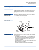
Quantum Bezel Replacement Guide Document 81-81252-05 A01 October 2006 Bezel Replacement Guide Overview Introduction 0 Naming Conventions Used in This Guide 0 0 This guide contains instructions for removing and installing front bezels for the SDLT 320, SDLT 600, DLT-S4, DLT VS160, and DLT-V4 tape drives. You can change the appearance of the tape drive by removing one bezel and replacing it with another. This guide uses specific terms to refer to parts of the tape drive and bezel.
Quantum Bezel Replacement Guide Document 81-81252-05 A01 October 2006 • Take electro-static discharge (ESD) precautions by ensuring that you are properly grounded before performing this operation. Static charge (for example, generated by your body, hair, and clothing) can transmit enough energy to damage the tape drive.
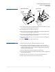
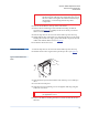
Quantum Bezel Replacement Guide Document 81-81252-05 A01 October 2006 Figure 2 SDLT 320 Removal Bottom right bezel tab Top right tab slot Top-cover tabs Top-cover tab slots Bottom right tab slot 3 Press down gently on the top right bezel tab and slowly pull the top right bezel corner out just enough to clear the slot. 4 Turn the tape drive over onto its right side. 5 Press down gently on the bottom left bezel tab and pull the bottom left bezel corner out just enough to clear the slot.
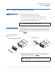
Quantum Bezel Replacement Guide Document 81-81252-05 A01 October 2006 SDLT 600/DLT-S4 Bezel Replacement Tools and Supplies Needed 0 Locate these tools and supplies before you begin: 0 • X-Acto® knife or small flat jeweler’s screwdriver • T-8 TORX®-bit screwdriver (supplied with SDLT 600 tape drives) • T-10 TORX-bit screwdriver (supplied with DLT-S4 tape drives) • DLTtape® decal (supplied with the tape drive).
Quantum Bezel Replacement Guide Document 81-81252-05 A01 October 2006 Caution: The lower right corner of the decal covers an opening into the infrared port of the tape drive (SDLT 600 only). Avoid this area when removing the decal. If the instrument slips into the hole, you can damage delicate tape drive components. 2 Place the decal adhesive-side up on the work surface. 3 Remove the two mounting screws from the bezel using a TORX-bit screwdriver (see figure 1).
Quantum Bezel Replacement Guide Document 81-81252-05 A01 October 2006 DLT VS160/DLT-V4 Bezel Replacement Tool Needed 0 Small flat-head screwdriver or similar tool. Note: Remove the Existing Bezel 0 0 The tape drive and bezel may look different from the illustration. The illustration shows an DLT VS160 tape drive. 1 Place the tape drive on its left side. 2 Hold the right side of the bezel.
Quantum Bezel Replacement Guide Document 81-81252-05 A01 October 2006 Install the New Bezel 0 1 Insert the left bezel tab into the left tab slot (see figure 2). Caution: Figure 2 VS160/DLT-V4 Install Left bezel tab Do not drag the bezel across the drive front panel. Seated tabs Top tab Door spring Right tab slot 2 Gently press in the right bezel tab and insert it into the right tab slot. 3 Make sure the tab on top of the tape drive fits into the slot on the top of the bezel (see figure 2).
Quantum Anleitung zum Austauschen der Verkleidung Dokument 81-81252-05 A01 Oktober 2006 Anleitung zum Austauschen der Verkleidung - Überblick Einführung 0 0 Diese Anleitung enthält Anweisungen für den Aus- und Einbau von FrontVerkleidungen für die Bandlaufwerke SDLT 320, SDLT 600, DLT-S4, DLT VS160 und DLT-V4. Sie können die Erscheinung des Bandlaufwerks durch Ausbau einer Verkleidung und Einbau einer anderen ändern.
Quantum Anleitung zum Austauschen der Verkleidung Dokument 81-81252-05 A01 Oktober 2006 • Der Austausch der Verkleidung kann nicht durchgeführt werden, solange sich das Band im Laufwerk befindet. • Treffen Sie Vorsichtsmaßnahmen gegen elektrostatische Entladung (ESD); stellen Sie dazu sicher, dass Sie vor der Durchführung dieses Vorgangs entsprechend geerdet sind. Statische Ladung (z. B. erzeugt durch Körper, Haar und Kleidung) kann genug Energie übertragen, dass das Bandlaufwerk beschädigt wird.
Quantum Anleitung zum Austauschen der Verkleidung Dokument 81-81252-05 A01 Oktober 2006 Verkleidungs-Sicherungsnase rechts unten Abbildung 2 SDLT 320 Ausbau SicherungsnasenSchlitz rechts oben Sicherungsnasen-Schlitz rechts unten Sicherungsnasen an der oberen Abdeckung Sicherungsnasen-Schlitze an der oberen Abdeckung 3 Drücken Sie leicht auf die Sicherungsnase rechts oben an der Verkleidung (durch den Schlitz) und ziehen Sie die rechte obere Ecke der Verkleidung gerade weit genug heraus, dass sie den Sc
Quantum Anleitung zum Austauschen der Verkleidung Dokument 81-81252-05 A01 Oktober 2006 SDLT 600/DLT-S4-Verkleidung - Austausch Erforderliche Werkzeuge und Verbrauchsmaterialien 0 Legen Sie diese Werkzeuge und Verbrauchsmaterialien bereit, bevor Sie beginnen: 0 • X-Acto®-Messer oder kleiner Juwelier-Schraubendreher mit flacher Klinge • T-8 TORX®-Bit Schraubendreher (im Lieferumfang der SDLT 600Bandlaufwerke) • T-10 TORX-®-Bit-Schraubendreher (im Lieferumfang der DLT-S4Bandlaufwerke) • DLTtape®-A
Quantum Anleitung zum Austauschen der Verkleidung Dokument 81-81252-05 A01 Oktober 2006 1 Führen Sie die Klinge eines Messers oder Juwelier-Schraubendrehers vorsichtig unter die linke Kante des Aufklebers, um ihn zu lösen (siehe Abbildung 1). Ziehen Sie den Aufkleber vorsichtig mit den Fingern von der Verkleidung. Anmerkung: Die linke Ecke des Aufklebers ist nicht mit Klebstoff bestrichen - dadurch wird das Abziehen erleichtert.
Quantum Anleitung zum Austauschen der Verkleidung Dokument 81-81252-05 A01 Oktober 2006 3 Schieben Sie die drei oberen Verkleidungs-Sicherungsnasen in ihre Schlitze in der oberen Abdeckung des Bandlaufwerks. 4 Senken Sie die Verkleidung in ihre Stellung ab. 5 Drehen Sie die beiden Verkleidungsbefestigungsschrauben ein und ziehen Sie sie mit dem TORX-Bit-Schraubendreher fest. Vorsicht: Nicht zu fest anziehen. Die Kunststoffverkleidung darf sich beim Festziehen der Schrauben nicht verbiegen.
Quantum Anleitung zum Austauschen der Verkleidung Dokument 81-81252-05 A01 Oktober 2006 Abbildung 1 VS160/DLTV4-Ausbau Rechter Sicherungsnasenschlitz 3 Nehmen Sie die Verkleidung vom Bandlaufwerk. Stellen Sie sicher, dass die Türfeder sich immer noch auf der Verkleidung befindet. Neue Verkleidung einbauen 0 1 Führen Sie die linke Verkleidungs-Sicherungsnase in den linken Sicherungsnasen-Schlitz ein (siehe Abbildung 2).
Guía de reemplazo del bisel, Quantum Documento 81-81252-05 A01 Octubre de 2006 Descripción general de la guía de reemplazo del bisel Introducción 0 Convenciones de los nombres que se usan en esta guía 0 0 Esta guía contiene instrucciones para quitar e instalar el bisel delantero de las unidades de cinta SDLT 320, SDLT 600, DLT-S4, DLT VS160 y DLT-V4. Usted puede cambiar el aspecto de la unidad de cinta retirando un bisel y sustituyéndolo por otro.
Guía de reemplazo del bisel, Quantum Documento 81-81252-05 A01 Octubre de 2006 • Tome las precauciones pertinentes contra descargas electrostáticas asegurándose que está usted conectado correctamente a tierra antes de realizar esta operación. Las cargas estáticas (por ejemplo, las generadas por el cuerpo, el cabello y la ropa) pueden transmitir suficiente energía para dañar la unidad de cinta.
Guía de reemplazo del bisel, Quantum Documento 81-81252-05 A01 Octubre de 2006 Figura 2 Desmontaje en la SDLT 320 Lengüeta inferior derecha del bisel Ranura de la lengüeta superior derecha Ranura de la lengüeta inferior derecha Lengüetas de la cubierta superior Ranuras de la lengüeta de la cubierta superior 3 Presione suavemente la lengüeta superior derecha del bisel y tire lentamente de la esquina superior derecha del bisel para alejarla apenas los suficiente para que salga de la ranura.
Guía de reemplazo del bisel, Quantum Documento 81-81252-05 A01 Octubre de 2006 Reemplazo del bisel de la SDLT 600/DLT-S4 Herramientas y materiales necesarios 0 Localice estas herramientas y materiales antes de comenzar: • Cortador X-Acto® o destornillador pequeño de punta plana, de tipo joyero • Destornillador de punta tipo T-8 TORX® (se incluye en las unidades de cinta SDLT 600) • Destornillador de punta tipo T-10 TORX (se incluye en las unidades de cinta DLT-64) • Etiqueta DLTtape® (se incluye co
Guía de reemplazo del bisel, Quantum Documento 81-81252-05 A01 Octubre de 2006 Precaución: La esquina inferior derecha de la etiqueta cubre la abertura que conduce al puerto de infrarrojos de la unidad de cinta (sólo en la SDLT 600). Evite el contacto con esta área al retirar la etiqueta. Si el instrumento resbala al interior del orificio, puede dañar componentes frágiles de la unidad de cinta. 2 Coloque la etiqueta sobre la superficie de trabajo con el lado adhesivo orientado hacia arriba.
Guía de reemplazo del bisel, Quantum Documento 81-81252-05 A01 Octubre de 2006 5 Inserte el dos tornillos de montaje del bisel y apriételos con el destornillador de punta TORX hasta que queden firmes. Precaución: No los apriete demasiado. Al apretar los tornillos, el bisel de plástico no debe doblarse. 6 Desprenda el protector del adhesivo de la nueva etiqueta y adhiérala al bisel.
Guía de reemplazo del bisel, Quantum Documento 81-81252-05 A01 Octubre de 2006 Instale el nuevo bisel 0 1 Introduzca la lengüeta izquierda del bisel en la ranura correspondiente (consulte la figura 2). Precaución: No arrastre el bisel de un extremo a otro del panel frontal de la unidad.
Guide de remplacement du cadre Quantum Document 81-81252-05 A01 Octobre 2006 Présentation du guide de remplacement du cadre 0 0 Ce guide contient des instructions relatives au retrait et à l'installation des cadres avant des lecteurs de bande SDLT 320, SDLT 600, DLT-S4, DLT VS160 et DLT-V4. Vous pouvez changer l'apparence du lecteur de bande en changeant le cadre.
Guide de remplacement du cadre Quantum Document 81-81252-05 A01 Octobre 2006 • Prenez les précautions relatives aux décharges électrostatiques en vérifiant que vous êtes correctement relié à la terre avant d'effectuer cette opération. Les charges électrostatiques (générées par le corps, les cheveux ou les vêtements, par exemple) peuvent transmettre suffisamment d'énergie pour endommager le lecteur de bande.
Guide de remplacement du cadre Quantum Document 81-81252-05 A01 Octobre 2006 Figure 2 Retrait du SDLT 320 Languette inférieure droite du cadre Encoche supérieure droite Encoche inférieure droite Languettes de la partie supérieure Encoches dans la partie supérieure 3 Appuyez doucement sur la languette du cadre située en haut à droite, et tirez lentement et suffisamment sur le coin supérieur droit du cadre pour dégager l'encoche. 4 Retournez le lecteur de bande sur son côté droit.
Guide de remplacement du cadre Quantum Document 81-81252-05 A01 Octobre 2006 Remplacement du cadre SDLT 600/DLT-S4 Outils et fournitures nécessaires 0 0 Procurez-vous les outils et fournitures suivants avant de commencer : • Couteau X-Acto® ou petit tournevis plat de bijoutier • Tournevis TORX® T-8 (fourni avec les lecteurs de bande SDLT 600) • Tournevis TORX T-10 (fourni avec les lecteurs de bande DLT-S4) • Autocollant DLTtape® (fourni avec le lecteur de bande).
Guide de remplacement du cadre Quantum Document 81-81252-05 A01 Octobre 2006 Attention : Le coin inférieur droit de l'autocollant masque une ouverture dans le port à infrarouge du lecteur de bande (SDLT 600 seulement). N'utilisez pas ce coin pour retirer l'autocollant. Si l'outil glisse dans l'orifice, vous risquez d'endommager les composants fragiles du lecteur de bande. 2 Placez l'autocollant sur la surface de travail, face adhésive vers le haut.
Guide de remplacement du cadre Quantum Document 81-81252-05 A01 Octobre 2006 Remplacement du cadre DLT VS160/DLT-V4 Outils nécessaires 0 0 Petit tournevis à tête plate ou outil similaire. Remarque : Le lecteur de bande et le cadre peuvent différer de l'illustration. L'illustration montre un lecteur de bande DLT VS160. Retrait du cadre existant 0 1 Placez le lecteur de bande sur son côté gauche. 2 Maintenez le côté droit du cadre.
Guide de remplacement du cadre Quantum Document 81-81252-05 A01 Octobre 2006 Installation du nouveau cadre 1 Insérez la languette gauche du cadre dans l'encoche gauche (voir figure 2). 0 Attention : Ne faites pas glisser le cadre sur le panneau avant du lecteur. Figure 2 Installation du VS160/DLT-V4 Languette gauche du cadre Languettes insérées Languette supérieure Ressort de la trappe Encoche droite 2 Appuyez doucement sur la languette droite du cadre et insérez-la dans l'encoche droite.
Quantum ベゼル交換ガイド 文書 81-81252-05 A01 2006 年 10 月 ベゼル交換ガイドの概要 はじめに 0 0 このガイドには、SDLT 320、SDLT 600、DLT-S4、DLT VS160、DLT-V4 テープドライブの前面ベゼルの取り外しと取り付けについての説明が記載さ れています。ベゼルを別のものに交換してテープドライブの外観を変えるこ とができます。 このガイドでは、テープドライブとベゼルの各部品を呼ぶ際に特定の用語を 使用します。図 1 に、このガイドで用いる用語を示します。 このガイドで用いる 0 命名規則 メモ : テープドライブ、ベゼルの外観は図と異なる場合があります。こ の図では、SDLT 600 テープドライブを示しています。 図 1 ドライブ用語 テープドライブ の左面 テープドライブの 後部 ベゼルの 左面 ベゼ ルの上部 ベゼル の底部 重要説明 0 テープドライブ の右面 ベゼルの 右面 作業を開始する前に、以降の説明をお読みください。この内容は、ベゼル交 換をより安全かつ容易にします。 • すべての説明をよく読み
Quantum ベゼル交換ガイド 文書 81-81252-05 A01 2006 年 10 月 • この作業を行う際は、静電気放電 (ESD) のための予防措置として作業者 自身に適切な接地を施してください。静電荷 ( 身体、毛髪、衣服などか ら発生する ) エネルギーにより、テープドライブに損傷を招く恐れがあ ります。 注意 : Quantum では、テープドライブを接地された ( 無電圧の ) 導 電性のある面やマットの上に置き、テープドライブに有害な 電荷を与えないよう作業者の手首に放電 ( 接地 ) ストラップ を着用されることを推奨します。 詳細情報 0 詳細については、www.quantum.com を参照してください。技術サポートは、 Quantum テクニカル サポートまでお問い合わせください。電話番号は変更 されている場合があります。最新のお問合せ先情報は、www.quantum.
Quantum ベゼル交換ガイド 文書 81-81252-05 A01 2006 年 10 月 底部右ベゼル タブ 図 2 SDLT 320 取り外し 上部右タブ スロット 上部カバー タブ 上部カバー タブ スロット 底部右タブ スロット 3 上部右ベゼルのタブを緩やかに押し下げ、スロット枠から外れる位置ま でこの上部右ベゼルの隅をテープドライブからゆっくりと引き離しま す。 4 テープドライブをひっくり返して右側を下にします。 5 底部左ベゼルのタブを緩やかに押し下げ、スロット枠から外れる位置ま でこの底部左ベゼルの隅をテープドライブから引き離します。 6 上部左ベゼルのタブを緩やかに押し下げ、スロット枠から外れる位置ま でこの上部左ベゼルの隅をテープドライブからゆっくりと引き離しま す。 7 上部カバーにある 3 つのベゼルタブを押下げて、スロットから外します ( 図 2 を参照 )。 8 テープドライブからベゼルを緩やかに取り外します。 新しいベゼルの取り付け 0 1 ドライブの後部を下にして前面が上になるように置きます。 2 上部左右のベゼルのタブを内側に押し込みます。同時に、上部カ
Quantum ベゼル交換ガイド 文書 81-81252-05 A01 2006 年 10 月 SDLT 600/DLT-S4 ベゼル交換 必要工具と備品 0 0 作業を開始する前に以下の工具をご用意ください。 • X-Acto® ナイフか小型の宝飾用マイナス ドライバ • T-8 TORX® ビット ドライバ (SDLT 600 テープドライブ付属 ) • T-10 TORX ビット ドライバ (DLT-S4 テープドライブ付属 ) • DLTtape® デカール ( テープドライブ付属 ) メモ : テープドライブ、ベゼルの外観は図と異なる場合があります。こ の図では、SDLT 600 テープドライブを示しています。 既存ベゼルの取り外し 0ベゼルは、2 本の取り付けねじでテープドライブに取り付けられています。 DLTtape デカールを適用すると、ねじ穴が隠れます。デカールは、接着剤 (PSA) で所定の位置に貼り付けられ、テープドライブに 2 回まではがして付 け直すことができます ( 図 1 を参照 )。 図 1 SDLT 600/DLT-S4 取 り外し 取り付けね
Quantum ベゼル交換ガイド 文書 81-81252-05 A01 2006 年 10 月 注意 : デカールの右下隅は、テープドライブ (SDLT 600 に限る ) の 赤外線ポートにつながる穴をふさいでいます。デカールをは がす際、この部分は残してください。この穴に誤って器具な どを差し込むと、壊れやすいテープドライブの部品を損傷さ せる恐れがあります。 2 接着剤が付いた面を上にしてデカールを作業台に置きます。 3 TORX ビット ドライバを使って、ベゼルから 2 つの取り付けネジを外し ます ( 図 1 を参照 )。このねじは、後でベゼルを取り付け直すときに使用 するため、なくさないようにとっておきます。 4 テープドライブの後部を下にして前面が上になるように置きます。 5 角度が 45° 度になるようにベゼル底部の端をテープドライブから持ち上 げます。ベゼルを 45° 度に保ったまま、緩やかに上部ベゼルの 3 つのタ ブをスロットから引き出し、ベゼルから取り外します ( 図 1 を参照 )。 6 デカールをベゼルに貼り直します。 新しいベゼルの取り付け 0 1 テープドライブの後部を
Quantum ベゼル交換ガイド 文書 81-81252-05 A01 2006 年 10 月 DLT VS160/DLT-V4 ベゼル交換 必要工具 0 0 小型のマイナス ドライバか、それに準ずる工具。 メモ : テープドライブ、ベゼルの外観は図と異なる場合があります。こ の図では、SDLT テープドライブを示しています。 既存ベゼルの取り外し 0 1 左側面を下にしてテープドライブを置きます。 2 ベゼルの左側を持ちます。ベゼルをテープドライブから引き離しながら、 右ベゼルのタブ(タブ スロットを通る)を緩やかに押し下げます ( 図 1 を参照 )。 注意 : テープドライブ中に折れて落ちる可能性のあるもの(鉛筆な ど)は使用しないでください。小型のマイナス ドライバか、 それに準ずる工具をご利用ください。 図 1 VS160/DLT-V4 取り外し 右タブ スロット 3 テープドライブからベゼルを取り外します。ドアのスプリングがベゼル の所定の位置にあることを確認します。 39
Quantum ベゼル交換ガイド 文書 81-81252-05 A01 2006 年 10 月 新しいベゼルの取り付け 0 1 左ベゼル タブを左タブのスロットに差し込みます ( 図 2 参照 )。 注意 : ドライブの前面パネル上でベゼルを引きずらないでください。 図 2 VS160/DLT-V4 取り付け 左ベゼル タブ 固定タブ 上部タブ ドア スプリング 右タブ スロット 2 緩やかに右ベゼルタブを押し込み、それを該当するタブスロットに差し 込みます。 3 テープドライブ上部の上のタブがベゼル上部のスロットに納まっている ことを確認してください ( 図 2 を参照 )。 4 ベゼルの防塵ドアの開閉が自在に行えることを確認し、ドア スプリング が所定の位置にあることを確かめます。 40
Quantum 베젤 교체 설명서 문서 81-81252-05 A01 2006 년 10 월 베젤 교체 설명서 개요 0 0 이 설명서에는 SDLT 320, SDLT 600, DLT-S4, DLT VS160 및 DLT-V4 테이프 드 라이브의 전면 베젤을 분리하고 설치하는 데 필요한 지침이 들어 있습니다 . 테 이프 드라이브의 베젤을 분리하고 다른 것으로 교체하여 외관을 바꿀 수 있습 니다 . 이 설명서에 사용된 이름 0 부여 방식 이 설명서에서는 테이프 드라이브와 베젤의 부품을 나타내는 특수한 용어를 사 용합니다 . 그림 1 에서는 이 설명서에 나오는 용어에 대해 설명합니다 . 소개 주 : 테이프 드라이브와 베젤의 모양이 여기에 표시된 그림과 다를 수도 있 습니다 . 그림에 표시된 모델은 SDLT 600 테이프 드라이브입니다 .
Quantum 베젤 교체 설명서 문서 81-81252-05 A01 2006 년 10 월 • 이 작업을 수행하기 전에 적절한 방식으로 접지하여 ESD( 정전기 방전 ) 주 의사항에 맞는 조치를 취해야 합니다 . 인체나 머리털 또는 의복에 의하여 발생하는 정전기의 에너지로도 충분히 테이프 드라이브의 손상을 가져올 수 있습니다 . 주의 : 자세한 내용 0 Quantum 은 테이프 드라이브를 접지 (0 볼트 ) 에 연결된 전도 체 표면이나 매트 위에 놓고 손목에 정전기 ( 접지 ) 스트랩을 감 아 해로운 정전기가 테이프 드라이브에 전달되지 않도록 주의할 것을 권장합니다 . 자세한 내용은 www.quantum.com 을 방문하십시오 . 기술적인 도움이 필요하시 면 Quantum 기술 지원부로 연락하시기 바랍니다 . 전화 번호가 자주 변경되니 www.quantum.com 에서 최신 연락처 정보를 확인하십시오 .
Quantum 베젤 교체 설명서 문서 81-81252-05 A01 2006 년 10 월 오른쪽 하단 베젤 탭 그림 2 SDLT 320 분리 상단 덮개 탭 오른쪽 상단 탭 슬롯 상단 덮개 탭 슬롯 오른쪽 하단 탭 슬롯 3 오른쪽 상단 베젤 탭을 살며시 누르고 슬롯을 통과할 수 있을 만큼만 베젤 의 오른쪽 상단 코너를 천천히 당깁니다 . 4 테이프 드라이브를 오른쪽으로 돌립니다 . 5 왼쪽 하단 베젤 탭을 살며시 누르고 슬롯을 통과할 수 있을 만큼만 베젤의 왼쪽 하단 코너를 천천히 당깁니다 . 6 왼쪽 상단 베젤 탭을 살며시 누르고 슬롯을 통과할 수 있을 만큼만 베젤의 왼쪽 상단 코너를 천천히 당깁니다 . 7 세 개의 상단 덮개 베젤 탭을 눌러서 슬롯으로부터 빠져 나오게 합니다 ( 그 림 2 참조 ). 8 테이프 드라이브에서 베젤을 살며시 빼냅니다 . 새 베젤 설치 0 1 드라이브의 전면이 위로 향하도록 뒤로 돌려 놓습니다 . 2 왼쪽과 오른쪽 상단 베젤 탭을 안쪽으로 누릅니다 .
Quantum 베젤 교체 설명서 문서 81-81252-05 A01 2006 년 10 월 SDLT 600/DLT-S4 베젤 교체 필요한 도구와 공급품 0 0 시작하기 전에 다음과 같이 도구와 공급품을 준비하십시오 . • X-Acto ® 나이프 또는 소형 일자 정밀 드라이버 • T-8 TORX ® - 비트 드라이버 (SDLT 600 테이프 드라이브와 함께 공급됨 ) • T-10 TORX- 비트 드라이버 (DLT-S4 테이프 드라이브와 함께 공급됨 ) • DLTtape ® 스티커 ( 테이프 드라이브와 함께 공급됨 ). 주 : 테이프 드라이브와 베젤의 모양이 여기에 표시된 그림과 다를 수도 있 습니다 . 그림에 표시된 모델은 SDLT 600 테이프 드라이브입니다 . 기존 베젤 분리 0두 개의 장착 나사로 베젤을 테이프 드라이브에 장착합니다 . 고정시킨 후에는 DLTtape 스티커를 붙여 나사가 보이지 않도록 합니다 .
Quantum 베젤 교체 설명서 문서 81-81252-05 A01 2006 년 10 월 2 스티커의 접착 부분이 위로 향하도록 놓습니다 . 3 TORX- 비트 드라이버를 사용하여 두 개의 장착 나사를 베젤로부터 제거합 니다 ( 그림 1 참조 ). 나사들을 주변에 잘 두었다가 베젤을 다시 장착할 때 사용합니다 . 4 테이프 드라이브의 전면이 위로 향하도록 뒤로 돌려 놓습니다 . 5 테이프 드라이브에서 베젤 하단 모서리를 45° 각도로 들어올립니다 . 베젤 을 45° 각도로 잡은채로 , 세 개의 상단 베젤 탭을 해당 슬롯으로 가볍게 밀 어 넣은 다음 베젤을 들어 올립니다 ( 그림 1 참조 ). 6 스티커를 베젤에 다시 부착합니다 . 새 베젤 설치 0 1 테이프 드라이브의 전면이 위로 향하도록 뒤로 돌려 놓습니다 . 2 테이프 드라이브 위로 베젤을 45° 각도로 잡습니다 ( 그림 2 참조 ).
Quantum 베젤 교체 설명서 문서 81-81252-05 A01 2006 년 10 월 DLT VS160/DLT-V4 베젤 교체 필요한 도구 0 0 소형 일자 드라이버나 그와 유사한 도구 . 주 : 테이프 드라이브와 베젤의 모양이 여기에 표시된 그림과 다를 수도 있 습니다 . 그림에 표시된 모델은 DLT VS160 테이프 드라이브입니다 . 기존 베젤 분리 0 1 테이프 드라이브를 왼쪽에 둡니다 . 2 베젤의 오른쪽을 잡습니다 . 오른쪽 베젤 탭을 가볍게 누르면서 ( 탭 슬롯을 통해 ) 베젤을 드라이브로부터 당깁니다 ( 그림 1 참조 ). 주의 : 연필 끝 부분과 같이 테이프 드라이브 내부에서 부러질 수 있는 도구는 일체 사용하지 마십시오 . 소형 일자 드라이버나 그와 유 사한 도구를 사용하십시오 . 그림 1 VS160/DLT-V4 분리 오른쪽 탭 슬롯 3 테이프 드라이브에서 베젤을 빼냅니다 . 도어 스프링이 베젤에 그대로 있는 지 확인합니다 .
Quantum 베젤 교체 설명서 문서 81-81252-05 A01 2006 년 10 월 새 베젤 설치 0 1 왼쪽 베젤 탭을 왼쪽 탭 슬롯에 삽입합니다 ( 그림 2 참조 ). 주의 : 그림 2 VS160/DLT-V4 설치 베젤을 드라이브 전면 패널 위로 잡아 끌지 마십시오 . 왼쪽 베젤 탭 삽입된 탭 상단 탭 도어 스프링 오른쪽 탭 슬롯 2 오른쪽 베젤 탭을 살며시 눌러 오른쪽 탭 슬롯에 삽입합니다 . 3 테이프 드라이브 상단에 있는 탭이 베젤의 상단에 있는 슬롯에 들어가 있는 지 확인 하십시오 ( 그림 2 참조 ). 4 먼지막이 문이 자유롭게 여닫히는지 확인하고 도어 스프링이 제자리에 있 는지 확인합니다 .
Quantum 前盖更换指南 文档 81-81252-05 A01 2006 年 10 月 前盖更换指南概述 简介 0 本指南中使用的命名约定 0 0 本指南包含为 SDLT 320、 SDLT 600、 DLT-S4、 DLT VS160 和 DLT-V4 磁带 机卸下和安装前盖的说明。您可以通过卸载前盖并更换为另一个,来更改磁带 机的外观。 本指南使用特定术语表示磁带机的部件和前盖。图 1 标识本指南中使用的术语。 注 : 磁带机和前盖在图示上可能不同。图示显示 SDLT 600 磁带机。 图 1 磁带机术语 磁带机左侧 磁带机后部 前盖左侧 前盖顶部 前盖底部 重要说明 0 磁带机右侧 前盖右侧 开始前请阅读以下说明。它们将有助于以更安全更容易地方式更换前盖。 • 仔细阅读并遵循所有说明。如果您在取下或更换前盖时损坏磁带机并因此 发生磁带机错误,您的保修期可能会失效。 • 使用适用于您磁带机型号的说明。这些说明差异显著。 • 请小心不要损坏或刮掉磁带机前部的前盖后表面安装的 LED。 • 安装磁带的情况下不能执行前盖更换。 • 请通过确保在执行此操作前正确
Quantum 前盖更换指南 文档 81-81252-05 A01 2006 年 10 月 有关更多信息 0 有关更多信息,请访问 www.quantum.com。有关技术帮助,请联系 Quantum 技术支持。电话号码更改频繁,有关最新联系信息,请访问 www.quantum.
Quantum 前盖更换指南 文档 81-81252-05 A01 2006 年 10 月 安装新前盖 0 1 将磁带机放置在其后部使磁带机前部向上。 2 向内按左上和右上前盖卡舌。同时,将三个顶盖前盖卡舌放置在其插槽 中。降低前盖底部,直到三个顶盖卡舌和左上及右上前盖卡舌滑入插槽。 3 向内按左下和右下前盖卡舌。 4 降低前盖底部直到左下和右下前盖卡舌滑入其插槽。 5 确保所有七个前盖卡舌牢固锁定在插槽中。 6 确保前盖防尘门打开并关闭自如。 SDLT 600/DLT-S4 前盖更换 所需工具和用品 0 0 开始前请找到下列工具和用品: • X-Acto® 刀或小平头宝石螺丝刀 • T-8 TORX®-bit 螺丝刀 (随 SDLT 600 磁带机提供) • T-10 TORX-bit 螺丝刀 (随 DLT-S4 磁带机提供) • DLTtape® 贴花 (随磁带机提供)。 注 : 磁带机和前盖在图示上可能不同。图示显示 SDLT 600 磁带机。 卸下现有前盖 0两个安装螺丝将前盖连接到磁带机。DLTtape 贴花在贴附后遮住螺丝。粘合剂 (PSA) 固定贴花,贴花可取
Quantum 前盖更换指南 文档 81-81252-05 A01 2006 年 10 月 1 请以刀锋或平头宝石螺丝刀在贴花左边缘下小心滑动以取下贴花 ( 参看 图 1)。使用手指将贴花从前盖上揭下。 注 : 贴花左边缘没有粘合剂;这样使取下更加容易。 警告 : 贴花右下角遮盖磁带机红外端口的开口 (仅 SDLT 600)。取 下贴花时请避开此区域。如果工具落入孔中,会损坏精密的磁 带机组件。 2 将贴花粘合面向上放置在工作平面。 3 用 TORX 螺丝刀 从外框去除二个安装的螺钉 ( 参看 图 1)。将螺丝小心放 在一旁,稍后将使用它们重新安装前盖。 4 将磁带机放置在其后部使磁带机前部向上。 5 将前盖底边缘提起与磁带机成 45° 角度。保持前盖 45° 角度,将三个顶部 前盖卡舌轻轻滑出其插槽并提起前盖 ( 参看图 1)。 6 将贴花重新贴在前盖上。 安装新前盖 0 1 将磁带机放置在其后部使磁带机前部向上。 2 保持前盖以磁带机的顶部的 45° 角度 ( 参看 图 2)。 图 2 SDLT 600/DLT-S4 安装 45° 3 将三个顶部前盖卡舌插入磁带机顶盖的插槽。 4 放下前
Quantum 前盖更换指南 文档 81-81252-05 A01 2006 年 10 月 DLT VS160/DLT-V4 前盖更换 所需工具 0 0 小平头螺丝刀或类似工具 注 : 磁带机和前盖在图示上可能不同。图示显示 DLT VS160 磁带机。 卸下现有前盖 0 1 将磁带机放在其左侧。 2 握住前盖右侧。将前盖拉离磁带机时轻轻按下右前盖卡舌 (通过卡舌插 槽) ( 参看图 1)。 警告 : 请勿使用任何可能破坏磁带机内部的工具 (如铅笔头)。请使 用小平头螺丝刀或类似工具。 图 1 VS160/DLT-V4 卸下 右卡舌插槽 3 从磁带机卸下前盖。证实门上弹簧仍然到位在外框上。 52
Quantum 前盖更换指南 文档 81-81252-05 A01 2006 年 10 月 安装新前盖 0 1 把左外框卡舌插入左舌插槽 ( 参看 图 2)。 警告 : 图 2 VS160/DLT-V4 安装 不要扯拽外框横跨出驱动器前面板。 左前盖卡舌 就位的卡舌 顶部卡舌 门弹簧 右卡舌 插槽 2 轻轻按下右前盖卡舌,插入到右卡舌插槽中。 3 确保磁带机顶部卡舌插入前盖顶部插槽 ( 参看 图 2)。 4 确保前盖防尘门打开并关闭自如 , 并且确保门的弹簧在位。 53
Quantum Bezel Replacement Guide Document 81-81252-05 A01 October 2006 Quantum Corporation provides this publication “as is” without warranty of any kind, either express or implied, including but not limited to the implied warranties of merchantability or fitness for a particular purpose. Quantum Corporation may revise this publication from time to time without notice. COPYRIGHT STATEMENT © Copyright 2006 by Quantum Corporation. All rights reserved.