COMMERCIAL COMMERCIAL INSTALLATION GUIDE 43 0001_QEco_D_C_LC_Owners_Manual_Warranty_A4_Spreads_72pp.
COMMERCIAL INSTALLATION GUIDE CONTENTS Section 1: Section 2: Appliance Details 1a: Commercial Owner’s Details 45 1b: Installer’s Details 45 1c: Service History 45 Installation Details 2a: General Install Requirements 2a1: Location 2a2: Corrosion Protection 2b: Air Flow 2c: Evaporator Drain 2d: Pressure and Temperature Relief (PTR valve) 2e: Expansion Control Valve (ECV) 2f: Cold Water Connection 2g: Pressure Reducing Valve 2h: Caution Regarding Glass Lining of Tank 2i: Suitability for Installation i
COMMERCIAL INSTALLATION GUIDE Section 1: APPLIANCE DETAILS For future convenience, please fill in the following details and retain with your original invoice. 1A: OWNER’S DETAILS Surname: ................................................................................................................................................... Given Name(s): ..................................................................................................................... Address: ................................
COMMERCIAL INSTALLATION GUIDE Section 2: INSTALLATION DETAILS Titan System Titan 1020 System 46 AS2712 LIC.2650 SAI GLOBAL Titan Split system AS3498 WMKA2531 SAI GLOBAL 0001_QEco_D_C_LC_Owners_Manual_Warranty_A4_Spreads_72pp.
COMMERCIAL INSTALLATION GUIDE 2a: General Install Requirements This water heater must be installed by a licensed tradesperson, and in accordance with: 1. AS/NZ 3500.4 National Plumbing and Draining Code, Part 4: Hot Water Supply Systems 2. AS/NZ 3500.4.2, National Plumbing and Draining Code, Part 4.2: Hot Water Supply systems – Acceptable Solutions. 3. Other relevant Australian standards, industry or local water supply regulations or codes for mains pressure storage tanks.
COMMERCIAL INSTALLATION GUIDE 2d: Pressure and Temperature Relief (PTR) Valve a. The Pressure and Temperature Relief Valve (see tank data label for rating), which is supplied with the unit, must be fitted and made accessible so that the release mechanism can be operated and, if required, the valve replaced. b. The outlet of the PTR valve must be suitably drained to remove the water discharged during the normal heating cycle. The valve thread is RP ½”/15mm and must be installed into the top front socket..
COMMERCIAL INSTALLATION GUIDE 2k: Tempering Valves a. The tempering valve should be fitted on the hot water outlet of the Quantum units to reduce water temperature to the temperature designated in (e.g., 50°C as per the Local plumbing code and all Federal, State requirements. b. Quantum recommends the use of high performance valves suitable for “Solar” type water heaters. 2l: Electrical Connections a. Quantum water heaters are designed for single-phase 220/240V 50Hz A/C supply only.
COMMERCIAL INSTALLATION GUIDE 2n: Caution Regarding Drilling the Outer Casing This is extremely important and MUST be adhered to without exception! DO NOT DRILL ANY HOLES IN OUTER METAL CASING DRILLING OF ANY HOLES WILL VOID WARRANTY Section 3: OPERATING INSTRUCTIONS 3a: Filling the Water Heater Open all hot water taps. Open isolating valve at the cold-water inlet and allow the water heater to fill until water flows through the system. Close each hot water tap after the air is expelled from its line.
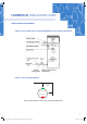
COMMERCIAL INSTALLATION GUIDE SINGLE TITAN INSTALL DIAGRAM: FIGURE 1: BASIC TANK LAYOUT WITH RECOMMENDED VALVES (EXCEPT TEMPERING) FIGURE 2: INSTALLATION DIAGRAM Suggested Distance from any Wall 500mm Cool Air Discharge Ambient Air Flow Tank Orientation Diagram for Titan Compact Units (Except Split Systems) 51 0001_QEco_D_C_LC_Owners_Manual_Warranty_A4_Spreads_72pp.
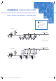
COMMERCIAL INSTALLATION GUIDE FIGURE 3: QUANTUM TITAN COMMERCIAL – CIRCULATING SYSTEM Legend Expansion Valve Tundish Check / Non-Return Valve Pressure Limiting Valve 1/4 Turn Ball Valve Isolation Valve Circulating Pump Hot Water Return 5 11 4 2 Hot Water Flow to Building 5 TD 6 6 8 6 5 1 2 3 Cold Water Supply Valves as per Australia / State / Territory standard 7 7 TANK 1 7 TANK 2 TANK 3 Hot Water Flow to Building 6 6 10 6 10 TANK 1 10 TANK 2 TANK 3 Hot Water Flow to Building Hot Wa
COMMERCIAL INSTALLATION GUIDE QUANTUM TITAN COMMERCIAL – CIRCULATING SYSTEM Header Sizes for Multiple Quantum Heat Pumps Number Of Heaters In Bank Nominal Size Of Headers 3 to 5 One pipe size larger than branch pipes Minimum Size Of Headers DN 25 6 to 10 Two pipe size larger than branch pipes 32 11 to 15 Three pipe size larger than branch pipes 40 Manifolded Titans Specifications Ref No.
COMMERCIAL INSTALLATION GUIDE FIGURE 4: HYDRONIC CONNECTION FOR 340-17ACW3-134 *Suggested Minimum Distance of 200mm between Tanks *Suggested Distance from any Wall 500mm Cool Air Discharge Ambient Air Flow Red “Alert” Lamp to face out from wall When installing a single Titan Compact unit the intake fan should always point out from, or along the wall. If the cold air discharge fan is facing towards a wall, the suggested distance between the unit and the wall is *500mm.
COMMERCIAL INSTALLATION GUIDE FIGURE 5: HYDRONIC CONNECTION FOR 1020-17ACW-134 AS2712 LIC.2650 SAI GLOBAL AS3498 WMKA2531 SAI GLOBAL 55 0001_QEco_D_C_LC_Owners_Manual_Warranty_A4_Spreads_72pp.
COMMERCIAL INSTALLATION GUIDE FIGURE 6: TITAN SPLIT SYSTEM (MODEL 340TIH-134 SHOWN) Other Split System Models available: Quantum recommends that the fan box should not extend more than 8m from the tank.
COMMERCIAL INSTALLATION GUIDE Appendix A: SPECIFICATIONS AND DIMENSIONS FIGURE 7: SPECIFICATIONS AND DIMENSIONS C C C A A A B B B 70mm MODEL NUMBER 70mm 70mm MASS (EMPTY (KG) MASS (FULL) (KG) R134a Charge (gm) 100 250 1650 150-08ACW-134 200-08ACW-134 115 315 1650 270-11AC3/4-134 135 405 1850 340-11AC3/4-134 170 510 1850 340-17ACW-134 190 535 2650 150-08ASW-134 90 240 1650 DIMENSIONS(MM) A B C 1620 975 540 1950 0 0 1900 2200 0 0 2240 1545 0 NOMINAL CAPACITY
COMMERCIAL INSTALLATION GUIDE FIGURE 8: SPLIT EVAPORATOR – FINNED COIL D B Air Flow A Refrigeration Connection C 3/8 ” Discharge Line Power Cable 5/8” Suction Line 100 50 110 40 150 A qualified refrigeration technician must install the Split Finned model. Whilst the plumbing and electrical work is the same as the Compact, this unit also requires on site refrigeration work.
COMMERCIAL INSTALLATION GUIDE FIGURE 10: WIRING DIAGRAM: 150/200-08ASW-134 & 340-17ASW-134 (340-TIH-134): FIGURE 11: WIRING DIAGRAM: 340-17ACW-134 59 0001_QEco_D_C_LC_Owners_Manual_Warranty_A4_Spreads_72pp.
COMMERCIAL INSTALLATION GUIDE FIGURE 12: INDICATOR 340-17ACW-134 / 340-ASW-134 Indicator light FIGURE 13: WIRING DIAGRAM – WITH TIMER: 150/200-08ACW-134 & 270/340-11AC4-134 60 0001_QEco_D_C_LC_Owners_Manual_Warranty_A4_Spreads_72pp.
COMMERCIAL INSTALLATION GUIDE FIGURE 14: WIRING DIAGRAM – WITH TIMER – 150/200-08ASW-134 & 270/340-11AS4-134 AS2712 LIC.2650 SAI GLOBAL AS3498 WMKA2531 SAI GLOBAL 0001_QEco_D_C_LC_Owners_Manual_Warranty_A4_Spreads_72pp.