Quality Control - Quantum 610 Inclusion of all Parts QUANTUM 610 Joystick Serial Number Controller Serial Number Left Motor Serial Number Right Motor Serial Number Fit and Finish Performance Pride keeps a more detailed report on file at the factory.
CONSIGNES DE SECURITE WARNING! A Pride Provider or a qualified technician must perform the initial setup of this power chair and must perform all of the procedures in this manual. The symbols below are used throughout this owner's manual and on the power chair to identify warnings and important information. It is very important for you to read them and understand them completely. WARNING! Indicates a potentially hazardous condition/situation.
CONTENTS I. INTRODUCTION I. INTRODUCTION ................................................................................................................................. 4 II. SAFETY .................................................................................................................................................. 5 III. YOUR POWER CHAIR .................................................................................................................... 17 IV. ASSEMBLY ..................
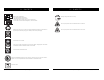
II. SAFETY II. SAFETY PRODUCT SAFETY SYMBOLS The symbols below are used on the power chair to identify warnings, mandatory actions, and prohibited actions. It is very important for you to read and understand them completely. Removal of grounding prong can create electrical hazard. If necessary, properly install an approved 3-pronged adapter to an electrical outlet having 2-pronged plug access. Read and follow the information in the owner’s manual. Wear safety goggles.
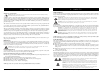
II. SAFETY II. SAFETY Battery Set Configuration: + = Positive (Red) Terminal Post - = Negative (Black) Terminal Post Connect Red wires to Red Positive (+) Terminal Posts. Connect Black wires to Black Negative (–) Terminal Posts. Battery charger for indoor use only. Do not place power chair in freewheel mode on a decline. Do not place power chair in freewheel mode on an incline.
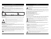
II. SAFETY II. SAFETY Weight Limitations Your power chair is rated for a maximum weight capacity. Please refer to the specifications table for this limit. Keep in mind that the maximum weight capacity includes the combined weight of the user and any accessories mounted to the power chair. GENERAL GUIDELINES MANDATORY! Do not operate your new power chair for the first time without completely reading and understanding this owner’s manual.
II. SAFETY II. SAFETY WARNING! If your power chair is equipped with a reclining seatback, do not attempt to negotiate inclines with the seat in a reclined position. Do not attempt to negotiate obstacles with the seat in a reclined position unless an attendant is present to help stabilize the chair. Failure to heed could result in the power chair tipping over. Public Streets and Roadways WARNING! You should not operate your power chair on public streets and roadways.
II. SAFETY II. SAFETY WARNING! Pride does not recommend using the power chair as a seat in a motor vehicle. The power chair user should transfer into the vehicle seat and use the vehicle-installed belt restraint system if and whenever feasible. WARNING! Always be sure your power chair and its batteries are properly secured when it is being transported. Batteries should be secured in an upright position and protective caps should be installed on the battery terminals.
II. SAFETY II. SAFETY Transfers Transferring onto and off of your power chair requires a good sense of balance. Always have an attendant or healthcare professional present while learning to properly transfer yourself. Flammability Precautions WARNING! Even though the plastics used on your power chair have been tested and have passed the applicable flammability standards, Pride recommends that you do not expose your power chair to open flames.
III. YOUR POWER CHAIR III. YOUR POWER CHAIR THE QUANTUM 610 The Quantum 610 has two main assemblies: the seat assembly and the power base assembly. See figure 5. Typically, the seat assembly includes the armrests, seatback, and seat base. The power base assembly includes two motor/brake assemblies, two drive wheels, four caster wheels, two batteries, and wiring harnesses. See figure 5, 6, and 7.
III. YOUR POWER CHAIR III. YOUR POWER CHAIR Main Circuit Breaker: The main circuit breaker is a safety feature built into your power chair. When the batteries and the motors are heavily strained (e.g., from excessive loads), the main circuit breaker trips to prevent damage to the motors and the electronics. If the circuit trips, allow your power chair to “rest” for approximately one minute. Next, push in the circuit breaker button, turn on the controller, and continue normal operation.
IV. ASSEMBLY IV. ASSEMBLY INITIAL ASSEMBLY Your power chair may require some assembly either before initial use or after transportation. It may also require disassembly to make some comfort adjustments. Figure 10 details those parts of the power chair that are designed to be disassembled and assembled by an end user or by a qualified caregiver before using the product or making comfort adjustments.
V. COMFORT ADJUSTMENTS IV. ASSEMBLY COMFORT ADJUSTMENTS After becoming familiar with your power chair’s operation, you may find the need to make some adjustments to increase your comfort, such as seat height and angle, armrest angle, foot platform height and angle, and controller position. If your power chair is equipped with power positioning options, refer to the information supplied in supplemental manuals or contact your Quantum Rehab Provider.
V. COMFORT ADJUSTMENTS V. COMFORT ADJUSTMENTS Seat Position You can move the seat forward or rearward by changing the extrusion mounting position. To change the armrest width: 1. Locate the two armrest knobs on each side of the armrest receiver bracket. See figure 18. 2. Loosen the knobs. 3. Slide the armrests in or out to the desired width. 4. Tighten the knobs. To change the position: 1. Turn off the power to the controller. 2. Loosen the rear shroud fasteners and remove the rear shroud. See figure 6.
V. COMFORT ADJUSTMENTS Foot Platform Height Adjustment The foot platform height is easily adjusted to different heights. To raise or lower the foot platform: 1. Remove the quick release fasteners from the foot platform bracket. See figure 20. 2. Loosen the foot platform securement nut one-half turn. 3. Raise or lower the foot platform to the desired height. 4. Reinstall the quick release fasteners into the foot platform bracket and tighten. 5. Tighten the nut to secure.
VI. BATTERIES AND CHARGING V. COMFORT ADJUSTMENTS BATTERIES AND CHARGING The Quantum 610 uses two long-lasting, 12-volt, deep-cycle batteries. These batteries are sealed and maintenance free. Since they are sealed, there is no need to check the electrolyte (fluid) level. Deep-cycle batteries are designed to handle a longer and deeper discharge. Though they are similar in appearance to automotive batteries, they are not interchangeable.
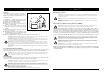
VI. BATTERIES AND CHARGING VI. BATTERIES AND CHARGING To charge the batteries using the off-board charger: 1. Position the front of your power chair next to a standard electrical outlet. 2. Be certain the controller power is turned off and the freewheel levers are in the engaged position. See III. “Your Power Chair.” 3. Plug the off-board charger into the off-board charger/ programming socket on the controller. See figure 25. 4. Plug the off-board charger into the electrical outlet.
VI. BATTERIES AND CHARGING VII. CARE AND MAINTENANCE How can I ensure maximum battery life? A fully charged deep-cycle battery will provide reliable performance and extended battery life. Keep your power chair’s batteries fully charged whenever possible. Batteries that are regularly and deeply discharged, infrequently charged, or stored without a full charge may be permanently damaged, causing unreliable power chair operation and limited battery life.
VII. CARE AND MAINTENANCE VII. CARE AND MAINTENANCE All wheel bearings are prelubricated and sealed. They require no subsequent lubrication. The body shroud has been sprayed with a clear sealant coating. You can apply a light coat of car wax to help it retain its high-gloss appearance. Check all electrical connections. Make sure they are tight and are not corroded. Batteries must sit flat within the battery tray, with the battery terminals facing inward, toward each other.
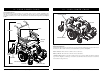
VII. CARE AND MAINTENANCE TIRE AXLE KEY VII. CARE AND MAINTENANCE WARNING! Do not mix old and new batteries. Always replace both batteries at the same time. REAR RIM HALF PROHIBITED! Keep tools and other metal objects away from the battery terminals. Contact with tools can cause electrical shock. TUBE AXLE SLOT FRONT RIM HALF WHEEL HUB NUTS DRIVE WHEEL NUT DRIVE WHEEL WASHER WASHERS Figure 26. Quantum 610 Drive Wheel Figure 27.
NOTES VII. CARE AND MAINTENANCE REAR SHROUD FASTENERS REAR SHROUD BATTERY WIRING DIAGRAM FRONT BATTERY REAR BATTERY Figure 28. Battery Installation Quantum 610 Series www.pridemobility.com 39 40 www.pridemobility.
NOTES Quantum 610 Series www.pridemobility.com NOTES 41 42 www.pridemobility.
CONSIGNES DE SECURITE WARNING! A Pride Provider or a qualified technician must perform the initial setup of this power chair and must perform all of the procedures in this manual. The symbols below are used throughout this owner's manual and on the power chair to identify warnings and important information. It is very important for you to read them and understand them completely. WARNING! Indicates a potentially hazardous condition/situation.
Quality Control - Quantum 610 Inclusion of all Parts QUANTUM 610 Joystick Serial Number Controller Serial Number Left Motor Serial Number Right Motor Serial Number Fit and Finish Performance Pride keeps a more detailed report on file at the factory.