
User's Guide


SCSI Interface Description Page 3
Signal Descriptions
The drive SCSI interface consists of eighteen signals. Nine are control lines and
eighteen are data lines. Data lines include the parity signal option. These signals are
described in the following table.
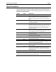
Signal Name Description
-BSY
Busy OR-tied signal used to show that the data bus is in use
-SEL
Select Signal used by an Initiator to select a Target or by a Target to
reselect an Initiator. SEL is driven by the Initiator during the
Selection Phase and driven by the Target during a Reselection
Phase.
-C/D
Control/Data Target-driven signal used to indicate whether Control or Data
information is on the data bus. True (low) indicates Control, and
false (high) indicates Data.
-I/O
Input/Output Target-driven signal used to control data movement direction on
the data bus with respect to an Initiator. This signal is also used to
distinguish between the Selection and Reselection Phases. True
(low) indicates input to the Initiator, and false (high) indicates
output from the Initiator.
-MSG
Message Target-driven signal used to indicate the presence of a Message
Phase on the bus. True (low) indicates Message Phase, and false
(high) indicates Data, Command, or Status Phase.
-REQ
Request Target-driven signal used to indicate a request for a REQ/ACK
data transfer handshake.
-ACK
Acknowledge Initiator-driven signal used to indicate an acknowledgment for a
REQ/ACK data transfer handshake.
-ATN
Attention Initiator-driven signal used to indicate the Initiator has a message
to communicate to the Target.
-RST
Reset OR-tied signal used to indicate a Reset condition.
DB(7-0)
Data Bus Eight data-bit signals plus a parity bit signal that form the odd
bytes of the data bus. DB (7) is the MSB and has the highest
priority (ID 7) during the Arbitration Phase.
DB(8-15)
Data Bus Eight data-bit signals that form the even byte of the data bus.
DB(15) is the MSB
DB(P0)
Data Bus The data parity bit for the odd byte of the data bus. Parity is odd
and is a jumper-selectable option. Parity is not valid during the
Arbitration Phase. DB (P) is not to be driven False (high) during
the Arbitration Phase.
DB(P1)
Data Bus Data parity bit for the even byte of the data bus.
NOTE: The BSY and RST signals are the only OR-tied signals. In ordinary bus operation, these
signals may be simultaneously driven by two or more drivers. There is no operational problem in mixing
OR-tied and three-state drivers on signals other than BSY and RST.