
User's Manual


Theory of operations
37
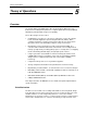
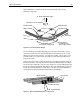
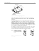
Figure 20 illustrates a helix track and the four-head design, and shows the
102-degree wrap angle.
6˚ Drum inclination angle
Direction of drum rotation:
102˚ Angle of tape wrap
Write Head B
Read Head A
Read Head B
Write Head A
Tape
Direction
Tape
Drum
Track of one
recording head
across tape surface
Figure 20. Four-Head Cylinder Design
The recorded tracks are written diagonally across the tape from bottom to top by
each write head. Because the head is wider than the track written, tracks overlap
with no tape space between them. In conventional recording, such overlap or even
proximity results in crosstalk (signals from adjacent tracks interfering with signals
from another track).
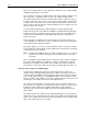
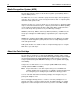
However, in helical scan recording, the heads are set at different azimuth angles so
that alternate tracks on the tape are written at alternate azimuth angles. (See Figure
21) Because the read head is set to the same angle as its corresponding write head,
it picks up a stronger signal from data written in the same azimuth angle as itself. So
it reads the track with minimal crosstalk. At the same time, the head is maintained
centered in the track by the timing tracking hardware and firmware.
Write head B
Write head A
20˚ head azimuth
3 tape tracks
Figure 21. Alternating Azimuth Angles on Tape Tracks