QUANTUM Litestream XF LITESTREAM XF ® *INFMANU2788* Product Serial #
SAFETY GUIDELINES WARNING! A Quantum Rehab Provider or a qualified technician must perform the initial setup of this wheelchair and must perform all of the procedures in this manual. The symbols below are used throughout this owner's manual and on the wheelchair to identify warnings and important information. It is very important for you to read them and understand them completely. WARNING! Indicates a potentially hazardous condition/situation.
CONTENTS I. INTRODUCTION ................................................................................................................................. 4 II. SAFETY .................................................................................................................................................. 6 III. YOUR WHEELCHAIR ..................................................................................................................... 15 IV. COMFORT ADJUSTMENTS .........................
I. INTRODUCTION SAFETY WELCOME to Quantum Rehab, a division of Pride Mobility Products (Pride). The wheelchair you have purchased combines state-of-the-art components with safety, comfort, and styling in mind. We are confident that these design features will provide you with the conveniences you expect during your daily activities. Once you understand how to safely operate and care for your wheelchair, it should give you years of trouble free operation and service.
I. INTRODUCTION United Kingdom: Pride Mobility Products Ltd. 32 Wedgwood Road Bicester, Oxfordshire OX26 4UL UK Australia: Pride Mobility Products Australia Pty. Ltd. 20-24 Apollo Drive Hallam, Victoria 3803 Australia NOTE: If you ever lose or misplace your copy of this manual, contact us and we will be glad to send you a new one immediately. Litestream XF www.pridemobility.
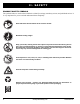
II. SAFETY PRODUCT SAFETY SYMBOLS The symbols below are used on the wheelchair to identify warnings, mandatory actions, and prohibited actions. It is very important for you to read and understand them completely. Read and follow the information in the owner’s manual. Maximum seating weight. Keep your hands, clothing and all other object away from the tires when driving. Do not allow any personal belongings or objects to drag behind the wheelchair when driving.
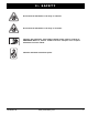
II. SAFETY Do not allow the wheelchair to roll freely on a decline. Do not allow the wheelchair to roll freely on an incline. Indicates that wheelchair, with similarly labeled seating system, conforms to ANSI/RESNA WC/Vol. 4, Section 19/ISO 7176-19 for transport of an occupied wheelchair in a motor vehicle. Indicates wheelchair securement points. Litestream XF www.pridemobility.
II. SAFETY GENERAL GUIDELINES MANDATORY! Do not operate your new wheelchair for the first time without completely reading and understanding this owner’s manual. Your wheelchair is a state-of-the-art life-enhancement device designed to increase mobility. Pride provides an extensive variety of products to best fit the individual needs of the wheelchair user.
II. SAFETY Weight Limitations Your wheelchair is rated for a maximum weight capacity. Please refer to the specifications table for this limit. Keep in mind that the maximum weight capacity includes the combined weight of the user and any accessories mounted to the wheelchair. MANDATORY! Stay within the specified weight capacity of your wheelchair. Exceeding the weight capacity voids your warranty.
II. SAFETY WARNING! If your wheelchair is equipped with a reclining seatback, do not attempt to negotiate inclines with the seat in a reclined position. Do not attempt to negotiate obstacles with the seat in a reclined position unless an attendant is present to help stabilize the chair. Failure to heed may result in the wheelchair tipping over. WARNING! If your wheelchair is equipped with an optional carry bag mounted to the seatback, do not overload the bag or exceed the maximum load rating of the bag.
II. SAFETY Outdoor Driving Surfaces Your wheelchair is designed to provide optimum stability under normal driving conditions—dry, level surfaces composed of concrete, blacktop, or asphalt. However, Pride recognizes that there will be times when you will encounter other surface types. For this reason, your wheelchair is designed to perform admirably on packed soil, grass, and gravel. Feel free to use your wheelchair safely on lawns and in park areas. Avoid driving on uneven terrain and/or soft surfaces.
II. SAFETY Doors Determine if the door opens toward or away from you. Drive your wheelchair gently and slowly forward to push the door open. Or drive your wheelchair gently and slowly backward to pull the door open. Elevators Modern elevators have a door edge safety mechanism that, when pushed, reopens the elevator door(s).
II. SAFETY WARNING! The positioning belt is not designed for use as a seat belt in a motor vehicle. Nor is your wheelchair suitable for use as a seat in any vehicle. Anyone traveling in a vehicle should be properly belted into seats approved by the vehicle manufacturer. Removable Parts WARNING! Do not attempt to lift or move a wheelchair by any of its removable parts, including the armrests, seat, and front riggings. Do not attempt to pick up the wheelchair while the seat is occupied.
II. SAFETY WARNING! Before transferring, position yourself as far back as possible in the wheelchair seat to prevent the wheelchair from tipping forward during transfer. WARNING! Avoid putting all of your weight on the wheelchair armrests and do not use the armrests for weight bearing purposes, such as transfers. Such use may cause the wheelchair to tip, resulting in a fall from the wheelchair and personal injury.
III. YOUR WHEELCHAIR THE LITESTREAM XF The Litestream XF is a dual-purpose, rear-wheel drive wheelchair designed to operate both indoors and outdoors on smooth surfaces. BACK CANE HANDLES SEATBACK ARMRESTS DRIVE WHEEL WHEEL LOCKS TIRE FRONT RIGGINGS (SWING-AWAY FOOTREST SHOWN) CASTER WHEEL HANDRIM SIDE FRAME CROSS FRAME FOOT PLATES CASTER FORK Figure 5. The Litestream XF Wheelchair Litestream XF www.pridemobility.
III. YOUR WHEELCHAIR USING THE LITESTREAM XF The Litestream XF is a manual wheelchair. Either an attendant pushes it, or you move it by gripping the hand-rims (see figure 5) and turning them in the desired direction of travel. You steer it by turning one wheel faster than the other. To stop the wheelchair, you apply pressure to both handrims until the wheelchair comes to a complete stop. PUSH FORWARD TO ENGAGE Unfolding The Litestream XF is a folding wheelchair. Unfold it completely before sitting in it.
III. YOUR WHEELCHAIR NOTE: If your wheelchair is equipped with a depthadjustable side frame, height-adjustable armrests, and waterfall armpads, interference may be encountered when attempting to fold the wheelchair. It may be necessary to remove the drive wheels to fold the wheelchair.
III. YOUR WHEELCHAIR Optional Caster Pin Lock If your wheelchair is equipped with a caster pin lock, you can lock the caster wheels in the forward position to aid in transferring. The caster pin lock should be engaged prior to transfer and disengaged prior to operating the wheelchair. To operate the caster pin lock: 1. Rotate the lever so that the securement pin is not in the groove to engage the caster pin lock. See figure 14. 2.
IV.
IV. COMFORT ADJUSTMENTS NOTE: If you change the drive wheel position, you may have to change the caster height and adjust the wheel lock. Consult your Quantum Rehab Provider. To change the drive wheel position: 1. Press the quick-release button and pull the drive wheel off. See figure 15. 2. Remove the center bolt and nut from the axle bracket. See figure 16. 3. Reposition the center bolt and nut forward or back to the desired position. 4. Tighten the center bolt and nut. 5. Reinstall the drive wheel.
IV. COMFORT ADJUSTMENTS Depth Adjustment Your Litestream XF may be equipped with a depthadjustable side frame. The depth adjustment range is 4 in. (10.16 cm) in 1-in (2.54-cm) increments. NOTE: The center of gravity of your wheelchair was factory set to a position that meets the needs of the demographic majority of users.
IV. COMFORT ADJUSTMENTS To adjust the anti-tip wheels: 1. Push the button on both sides of the anti-tip wheel at the same time and move the anti-tip wheel up or down to unlock it. See figure 20. 2. Adjust the anti-tip wheel to the desired position while aligning the anti-tip wheel with the adjustment holes. 3. Ensure that both buttons lock into place. You will hear a click when the anti-tip wheel is locked into place. 4.
IV. COMFORT ADJUSTMENTS Swing-Away Footrest (SFR) Removal The swing-away footrests (SFR) can be moved or removed to aid in transfers or transporting your wheelchair. To move the SFR to the side: 1. Push the release lever back. See figure 22. 2. Move the SFR aside. 3. Repeat for the other side if necessary. To remove the SFR: 1. Move the SFR to the side. NOTE: If your wheelchair is equipped with the ultra hemi option, the SFR must be facing forward and not swung to the side for removal. Figure 22.
IV. COMFORT ADJUSTMENTS Elevating Leg Rest (ELR) Angle You can change the ELR angle. See figure 26. To change the ELR angle: 1 To raise, pull the ELR up to the desired position. 2. To lower, pull the ELR release lever and lower the ELR to the desired position. WARNING! Use care when operating. Possible pinch point created during operation. SCREWS Elevating Leg Rest (ELR) Calf Pad You can change the height and depth of the ELR calf pad. See figures 27 and 28. To change the ELR calf pad height: 1.
IV. COMFORT ADJUSTMENTS Angle Adjustable Foot Plates The angle adjustable foot plates have two adjustments: angle and depth. The depth can be adjusted to four (4) positions in 1-in. (2.54 cm) increments. If the position of the foot plate adapter is reversed, an additional 0.75 in. (2 cm) of depth can be achieved at the most forward and most rearward positions. See figure 29. The foot plates can also be flipped up for ease of transfer. See figure 29. To adjust the foot plate angle: 1.
IV. COMFORT ADJUSTMENTS Drop-in Armrest Removal The drop-in armrests can be removed to aid in transfers or transporting your wheelchair. To remove the armrest: 1. Squeeze the armrest latch. See figure 32. 2. Pull the armrest up. 3. Repeat for the other side if necessary. ARMREST LATCH WARNING! Use care when operating. Possible pinch point created during operation. Drop-in Armrest Height Adjustment You can adjust the drop-in armrest height to five positions in 1-in. (2.54-cm) increments. Figure 32.
IV. COMFORT ADJUSTMENTS Flip-up Armrest Angle Adjustment You can adjust both the latching and non-latching flipup armrest angle. To adjust the non-latching flip-up armrest angle: 1. Flip up the armrest. 2. Turn the adjusting screw to raise or lower the front of the armrest. See figure 35. 3. Repeat for the other side if necessary. To adjust the latching flip-up armrest angle: 1. Push the armrest latch toward the front of the armrest and flip up the armrest until you hear a click. See figure 11. 2.
IV. COMFORT ADJUSTMENTS To adjust the dual-post armrest height: 1. Rotate the release lever that is located on the armrest in either direction. See figure 38. 2. Move the armrest up or down to the desired height. 3. The release lever is spring-loaded and will automatically release. 4. Make sure the armrest latches into place. 5. Repeat the procedure for the other side if necessary. RELEASE LEVER Seat Angle (Dump) Adjustment The position of the caster wheels affects the angle (dump) of the seat.
IV. COMFORT ADJUSTMENTS Caster Angle Adjustment When you change the seat angle, you must also change the caster angle so that the caster barrels remain at a 90° angle to the ground. See figure 40. There are 7 possible angles with a quick-release caster and 13 possible angles with a bolt-on caster. SCREWS NOTE: There are two screws that fasten the caster barrel assembly to the frame. The nuts that secure the screws are eccentric.
IV. COMFORT ADJUSTMENTS Positioning Belt Your wheelchair may be equipped with a positioning belt that can be adjusted for operator comfort. See figure 43. The positioning belt is designed to support the operator so that he/she does not slide down or forward in the seat. The positioning belt is not designed for use as a restraining device in a motor vehicle.
V. CARE AND MAINTENANCE CARE AND MAINTENANCE Your Litestream XF requires routine maintenance checks. You can perform some of these checks, but others require assistance from your Quantum Rehab Provider. Preventive maintenance is very important. If you follow the maintenance checks in this section as scheduled, you can help ensure that your wheelchair gives you years of trouble-free operation. If you have any doubt as to your wheelchair’s care or operation, contact your Quantum Rehab Provider.
V. CARE AND MAINTENANCE Check the handrims. Make sure that they are fastened securely to the wheels. Check the wheel locks. Make sure they work properly. If they don’t, instructions on how to adjust them are provided in this manual. WARNING! The wheel locks are designed to keep your chair stationary while you are parked. They are not designed to stop the wheelchair during driving. Do not use either of the wheel locks to stop the wheelchair while driving it.
V. CARE AND MAINTENANCE WARNING! Never use any chemicals to clean a vinyl seat, as they may cause the seat to become slippery or dry out and crack. Use soapy water and dry the seat thoroughly. Wheel Replacement Your wheelchair may be equipped with a tire and tube, tire and flat-free insert, or a solid polyurethane tire. Replacement tires, tubes, inserts, and tire assemblies are readily available through your Quantum Rehab Provider.
V. CARE AND MAINTENANCE WARNING! A Quantum Rehab Provider should adjust the wheel lock with the occupant in the wheelchair on the maximum incline to ensure that the wheel lock catches properly. To adjust each scissor-style wheel lock: 1. Disengage the wheel lock. The front of the wheel lock extrusion that faces the caster wheels should be exactly 2.1 in. (5.3 cm) from where the wheel lock blade makes contact with the plane of the drive wheel. See figure 46. This applies to both solid and pneumatic tires.
APPENDIX I - SPECIFICATIONS LITESTREAM XF SPECIFICATIONS (WITHOUT DEPTH-ADJUSTABLE SIDE FRAME) 1 2 3 Seat Dimensions: Width: 14-21 in.; 18-22 in. with HD option Depth: 14-20 in.; 18-20 in. with HD option Back Height: 15-19 in.; 12-16 in.; 15-19 in. with HD option Seat and Seatback: Adjustable tension Drive Wheels: Mags: 20 in. (50.8 cm), 22 in. (55.88 cm), and 24 in. (60.96 cm) Spoke: 20 in. (50.8 cm), 22 in. (55.88 cm), 24 in. (60.96 cm), 25 in. (63.5 cm), and 26 in. (66.
APPENDIX I - SPECIFICATIONS LITESTREAM XF SPECIFICATIONS (WITH DEPTH-ADJUSTABLE SIDE FRAME) Seat Dimensions: Width: 14-21 in. Depth: 14-20 in.; 3 in. (7.62 cm) of depth adjustment Back Height: 16-24 in. Seat and Seatback: Seat: Adjustable tension; Seatback: Synergy® Shape Back or similar back Drive Wheels: Mags: 20 in. (50.8 cm), 22 in. (55.88 cm), and 24 in. (60.96 cm) Spoke: 20 in. (50.8 cm), 22 in. (55.88 cm), 24 in. (60.96 cm), 25 in. (63.5 cm), and 26 in. (66.04 cm) Caster Wheels: Solid: 4 in.
APPENDIX I - SPECIFICATIONS LENGTH 39 in. (99.06 cm) TURNING RADIUS 22.5 in. (57.15 cm) WIDTH 26.5 in. (37.31 cm) Figure 48. Litestream XF Dimensions and Ground Clearance Litestream XF www.pridemobility.
APPENDIX II - STF HEIGHT MATRIX LITESTREAM XF SEAT-TO-FLOOR/AXLE PLATE MOUNTING MATRIX Axle Plate Mounting Location 20 in. Wheel 22 in. Wheel 24 in. Wheel ** 25 in. Wheel 26 in. Wheel 12.5 in. (31.75 cm) 13.5 in. (34.29 cm) 14.5 in. (36.83 cm) 15 in. (38.1 cm) 15.5 in. (39.37 cm) 13 in. (33.02 cm) 14 in. (35.56 cm) 15 in. (38.1 cm) 15.5 in. (39.37 cm) 16 in. (40.64 cm) 13.5 in. (34.29 cm) 14.5 in. (36.83 cm) 15.5 in. (39.37 cm) 16 in. (40.64 cm) 16.5 in. (41.91 cm) 14 in. (35.
APPENDIX II - STF HEIGHT MATRIX LITESTREAM XF SEAT-TO-FLOOR/AXLE PLATE MOUNTING MATRIX Axle Plate Mounting Location 20 in. Wheel 22 in. Wheel 24 in. Wheel ** 25 in. Wheel 26 in. Wheel 14.5 in. (36.83 cm) 15.5 in. (39.37 cm) 16.5 in. (41.91 cm) 17 in. (43.18 cm) 17.5 in. (44.45 cm) 15 in. (38.1 cm) 16 in. (40.64 cm) 17 in. (43.18 cm) 17.5 in. (44.45 cm) 18 in. (45.72 cm) 15.5 in (39.37 cm) 16.5 in. (41.91 cm) 17.5 in. (44.45 cm) 18 in. (45.72 cm) 18.5 in. (46.99 cm) 16 in. (40.
APPENDIX II - STF HEIGHT MATRIX LITESTREAM XF CASTER WHEEL FRONT SEAT-TO-FLOOR HEIGHT MATRIX Caster Size STF Height 4 in. 5 in. 6 in. 8 in. 12.5 in. 2US - - - 13 in. 1US, 3UF 2US - - 13.5 in. 3UL, 2UF 1US, 4UL - - 14 in. 2UL, 1UF 3UL, 2UF 1US, 4UL - 14.5 in. 1UL 2UL, 1UF 3UL - 15 in. 3S 1UL 2UL, 1UF - 15.5 in. 2S - 1UL - 16 in. 1S, 3F 2S - 2UL 16.5 in. 3L, 2F 1S, 4L - 1UL 17 in. 2L, 1F 3L, 2F 1S, 4L - 17.5 in. 1L 2L, 1F 3L - 18 in.
NOTES Litestream XF www.pridemobility.
NOTES 42 www.pridemobility.
SAFETY GUIDELINES WARNING! A Quantum Rehab Provider or a qualified technician must perform the initial setup of this wheelchair and must perform all of the procedures in this manual. The symbols below are used throughout this owner's manual and on the wheelchair to identify warnings and important information. It is very important for you to read them and understand them completely. WARNING! Indicates a potentially hazardous condition/situation.
QUANTUM Litestream XF LITESTREAM XF ® *INFMANU2788* Product Serial #