Quality Control - Quantum R-4000 Series Inclusion of all Parts QUANTUM SERIES Joystick Serial Number Controller Serial Number Left Motor Serial Number Right Motor Serial Number Fit and Finish Performance Pride keeps a more detailed report on file at the factory.
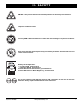
SAFETY GUIDELINES WARNING! A Quantum Rehab Provider or a qualified technician must perform the initial setup of this power chair and must perform all of the procedures in this manual. The symbols below are used throughout this owner's manual and on the power chair to identify warnings and important information. It is very important for you to read them and understand them completely. WARNING! Indicates a potentially hazardous condition/situation.
CONTENTS I. INTRODUCTION ................................................................................................................................... 4 II. SAFETY .................................................................................................................................................... 5 III. YOUR POWER CHAIR ...................................................................................................................... 18 IV. ASSEMBLY ..............................
I. INTRODUCTION SAFETY WELCOME to Quantum Rehab, a division of Pride Mobility Products Corporation (Pride). The power chair you have purchased combines state-of-the-art components with safety, comfort, and styling in mind. We are confident that these design features will provide you with the conveniences you expect during your daily activities. Once you understand how to safely operate and care for your power chair, it should give you years of trouble-free operation and service.
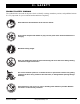
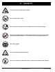
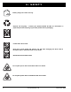
II. SAFETY PRODUCT SAFETY SYMBOLS The symbols below are used on the power chair to identify warnings, mandatory actions, and prohibited actions. It is very important for you to read and understand them completely. Read and follow the information in the owner’s manual. Do not allow unsupervised children to play near the power chair while the batteries are charging. Maximum seating weight. Keep your hands away from the tires when driving.
II. SAFETY Pinch/Crush points created during assembly. Do not remove anti-tip wheels. Do not connect an extension cord to the AC/DC converter or the battery charger. Removal of grounding prong can create electrical hazard. If necessary, properly install an approved 3-pronged adapter to an electrical outlet having 2-pronged plug access. Wear safety goggles. Corrosive chemicals contained in battery. Do not use a cell phone, walkie/talkie, laptop, or other radio transmitter while operating. 6 www.
II. SAFETY EMI-RFI - This product has been tested and passed at an immunity level of 20 V/m. Explosive conditions exist! Use only AGM or Gel-Cell batteries to reduce the risk of leakage or explosive conditions. Keep tools and other metal objects away from battery terminals. Contact with tools can cause electrical shock.
II. SAFETY Battery charger for indoor use only. Disposal and recycling — Contact your Quantum Rehab Provider for information on proper disposal and recycling of your Pride product and its packaging. Locked and in drive mode. Place unit on level ground and stand to one side when changing from drive mode to freewheel mode or freewheel mode to drive mode. Unlocked and in freewheel mode. Do not place power chair in freewheel mode on a decline. Do not place power chair in freewheel mode on an incline.
II. SAFETY Contains Lead. No step. No standing. Keep off! Quantum R-4000 www.pridemobility.
II. SAFETY GENERAL GUIDELINES MANDATORY! Do not operate your new power chair for the first time without completely reading and understanding this owner’s manual. Your power chair is a state-of-the-art life-enhancement device designed to increase mobility. Pride provides an extensive variety of products to best fit the individual needs of the power chair user.
II. SAFETY Weight Limitations Your power chair is rated for a maximum weight capacity. Please refer to the specifications table for this limit. Keep in mind that the maximum weight capacty includes the combined weight of the user and any accessories mounted to the power chair. MANDATORY! Stay within the specified weight capacity of your power chair. Exceeding the weight capacity voids your warranty.
II. SAFETY WARNING! Never travel down an incline backward. Doing so may cause the powerchair to tip. Always exercise extreme caution when negotiating an incline. WARNING! If your power chair is equipped with a reclining seatback, do not attempt to negotiate inclines with the seat in a reclined position. Do not attempt to negotiate obstacles with the seat in a reclined position unless an attendant is present to help stabilize the chair. Failure to heed could result in the power chair tipping over.
II. SAFETY WARNING! When cornering sharply, reduce your speed and maintain a stable center of gravity. This greatly reduces the possibility of a tip or fall. Public Streets and Roadways WARNING! You should not operate your power chair on public streets and roadways. Be aware that it may be difficult for traffic to see you when you are seated on your power chair. Obey all local pedestrian traffic rules. Wait until your path is clear of traffic, and then proceed with extreme caution.
II. SAFETY Figure 2. Correct Curb Approach Figure 3. Incorrect Curb Approach WARNING! Even though your power chair may be capable of handling greater obstacles, Pride recommends that you do not attempt to negotiate a curb that has a height greater than 2 in. (5 cm). Doing so could cause instability in your power chair. WARNING! Do not attempt to have your power chair proceed rearward down any step, curb, or other obstacle. This may cause the power chair to tip.
II. SAFETY Motor Vehicle Transport Pride recommends that you do not remain seated in your power chair while traveling in a motor vehicle. The power chair should be stowed in the trunk of a car or in the back of a truck or van with batteries removed and properly secured. In addition, all removable power chair parts, including the armrests, seat, front riggings, controller, and shrouds should be removed and/or properly secured during motor vehicle transport.
II. SAFETY Transfers Transferring onto and off of your power chair requires a good sense of balance. Always have an attendant or healthcare professional present while learning to properly transfer yourself. To eliminate the possibility of injury, Pride recommends that you or a trained attendant perform the following tasks before attempting a transfer: Turn off the power to the controller. Ensure your power chair is not in freewheel mode. See III. “Your Power Chair.
II. SAFETY Reaching and Bending Never reach, lean, or bend while driving your power chair. If it is absolutely necessary to reach, lean, or bend while seated on your power chair, it is important to maintain a stable center of gravity and keep the power chair from tipping. Pride recommends that the power chair user determine his/her personal limitations and practice bending and reaching in the presence of a qualified healthcare professional.
III. YOUR POWER CHAIR THE QUANTUM R-4000 SERIES POWER CHAIR Your power chair has two main assemblies: the seat and the power base. See figures 5 and 6. Typically, the seat assembly includes the armrests, seatback, and seat base. The power base assembly includes two motor/brake assemblies, two drive wheels, two anti-tip wheels, two caster wheels, two batteries, and wiring harnesses.
III. YOUR POWER CHAIR CONTROLLER CONNECTOR FRONT TRAPEZE BAR FRONT SHROUD MANUAL FREEWHEEL LEVER MOTOR/BRAKE ASSEMBLY MAIN CIRCUIT BREAKER Figure 6. The Quantum R-4000 Power Base BATTERY DOOR LATCH LOCATION CONTROLLER HARNESS ANTI-TIP WHEEL BATTERY DOOR LATCH BATTERY DOOR ANTI-TIP WHEEL Figure 7. The Quantum R-4000 Power Base (Rear View - Battery Door Down) Quantum R-4000 www.pridemobility.
III. YOUR POWER CHAIR Electrical Components The electrical components are located on the front of the power base or on the battery door at the rear of the power base depending on the power chair electrical system. See figures 6 and 7. Main Circuit Breaker: The main circuit breaker is a safety feature built into your power chair. When the batteries and the motors are heavily strained (e.g., from excessive loads), the main circuit breaker trips to prevent damage to the motors and the electronics.
III. YOUR POWER CHAIR Figure 8. Freewheel Mode (Drive Disengaged) - Hammer Motor Figure 9. Drive Mode (Drive Engaged) - Hammer Motor Figure 10. Freewheel Mode (Drive Disengaged) - Glide Motor Figure 11. Drive Mode (Drive Engaged) - Glide Motor Quantum R-4000 www.pridemobility.
IV. ASSEMBLY Seat Installation It may be necessary to install the seat either prior to initial operation or after transporting your power chair. NOTE: If your power chair is equipped with a Specialty Seat, Synergy Seat, or a Synergy TRU-Balance 2 Power Positioning System, refer to the information provided in separate manuals. NOTE: Any nylon insert lock nut removed during the disassembly or adjustment of the power chair must be replaced with a new nut.
V. COMFORT ADJUSTMENTS COMFORT ADJUSTMENTS After becoming familiar with your power chair’s operation, you may find the need to make some adjustments to increase your comfort, such as seat height and angle, armrest width, armrest angle and height, leg rest position, and controller position. NOTE: If your power chair is equipped with a Specialty Seat, Synergy Seating System, or TRU-Balance 2 Power Positioning System, refer to the seat adjustment information contained in separate manuals.
V. COMFORT ADJUSTMENTS 10. Loosen the shroud fasteners and remove the front shroud from the power base. 11. Remove the hardware from the front trapeze bar. 12. Raise or lower the front trapeze bar to the desired position. NOTE: To change the angle, set either the front or rear trapeze bar higher or lower than the other. 13. Reinstall the hardware into the front trapeze bar. 14. Place the seat back onto the trapeze bars and flip down the seat latch safety. 15. Reinstall the front shroud. 16.
V. COMFORT ADJUSTMENTS Seatback Angle Adjustment If your power chair is equipped with an adjustable seatback, you can adjust it to four (4) different angles: 90°, 102°, 105°, or 107°. To adjust the seatback angle: 1. Remove the adjusting screws from each seat hinge. See figure 18. 2. Set the seatback at the desired angle. 3. Reinstall the adjusting screws to each seat hinge and tighten. Armrest Width Adjustment You can change each armrest’s width independently of the other.
V. COMFORT ADJUSTMENTS Controller Position You can move the controller in toward or out away from the armrest, or change the position of the controller for either left-hand or right-hand use. WARNING! Do not place the controller harness so that it can be pinched in the seat frame or the power base frame. CONTROLLER BRACKET To extend the controller: 1. Flip up the armrest so it is perpendicular to the floor. 2. Loosen the setscrew on the controller bracket. See figure 19. 3.
V. COMFORT ADJUSTMENTS Anti-Tip Wheels The anti-tip wheels are designed to give your power chair increased stability on rough surfaces. The anti-tip wheels are preset at the factory for smooth surfaces or indoor use only. If you plan on using your power chair on rough surfaces, it may be necessary to adjust the anti-tip wheels to better suit your needs. The anti-tip wheels may need adjustment if either of the following occur: When accelerating, your power chair tips rearward excessively.
VI. BATTERIES AND CHARGING BATTERIES AND CHARGING The Quantum R-4000 uses two long-lasting, 12-volt, deep-cycle batteries. These batteries are sealed and maintenance free. Since they are sealed, there is no need to check the electrolyte (fluid) level. Deep-cycle batteries are designed to handle a longer and deeper discharge. Though they are similar in appearance to automotive batteries, they are not interchangeable.
VI. BATTERIES AND CHARGING To charge the batteries using the off-board charger: 1. Position the front of your power chair next to a standard electrical outlet. 2. Be certain the controller power is turned off and the freewheel levers are in the drive position. See III. “Your Power Chair.” 3. Plug the off-board charger into the off-board charger/programming socket on the controller. See figure 22. 4. Plug the off-board charger into the electrical outlet.
VI. BATTERIES AND CHARGING How often must I charge the batteries? Many factors come into play when deciding how often to charge the batteries. You may use your power chair all day on a daily basis or you may not use it for weeks at a time. Daily Use If you use your power chair on a daily basis, charge the batteries as soon as you are finished using your power chair. Your power chair will be ready each morning to give you a full day’s service.
VI. BATTERIES AND CHARGING How can I ensure maximum battery life? A fully charged deep-cycle battery will provide reliable performance and extended battery life. Keep your power chair’s batteries fully charged whenever possible. Batteries that are regularly and deeply discharged, infrequently charged, or stored without a full charge may be permanently damaged, causing unreliable power chair operation and limited battery life.
VII. CARE AND MAINTENANCE CARE AND MAINTENANCE Your Quantum R-4000 is a sophisticated power chair. Like any motorized vehicle, it requires routine maintenance checks. You can perform some of these checks, but others require assistance from your Quantum Rehab Provider. Preventive maintenance is very important. If you follow the maintenance checks in this section as scheduled, you can help ensure that your power chair gives you years of trouble-free operation.
VII. CARE AND MAINTENANCE All wheel bearings are prelubricated and sealed. They require no subsequent lubrication. The body shroud has been sprayed with a clear sealant coating. You can apply a light coat of car wax to help it retain its high-gloss appearance. Check all electrical connections. Make sure they are tight and are not corroded. Batteries must sit flat within battery boxes, with the battery terminals facing the top of the battery box.
VII. CARE AND MAINTENANCE Storage Your power chair should be stored in a dry place, free from temperature extremes. When storing, disconnect the batteries from the power chair. See VI. “Batteries and Charging.” WARNING! If you fail to store the unit properly, the frame can rust and the electronics can be damaged.
VII. CARE AND MAINTENANCE TIRE TUBE SCREWS FRONT RIM HALF WHEEL HUB REAR RIM HALF LUG NUT Figure 23. Quantum R-4000 Drive Wheel Figure 24. Quantum R-4000 Drive Wheel Disassembled Follow these easy steps for a quick and safe repair for both pneumatic and solid tires: 1. Turn off the power to the controller. 2. Set the power chair up on blocks. 3. If you are changing a pneumatic tire, completely deflate it before removing the wheel. 4. Remove the five (5) lug nuts from the wheel hub. See figure 23. 5.
VII. CARE AND MAINTENANCE To replace the batteries: 1. Turn off the power to the controller. 2. Push the manual freewheel lever in or up for drive mode. 3. Remove or rotate the leg rests to the side. 4. Release the battery door latches at the back of the power chair. 5. Locate the battery quick disconnects on the frame and disconnect both of them. See figure 25. 6. Remove the batteries from the power base. 7. Disconnect the battery wiring harness from each battery. 8.
APPENDIX I - SPECIFICATIONS SPECIFICATIONS 1 2 3 4 5 6 Suspension: Full suspension - Sport Trac Drive Wheels: 14 in. (35.5 cm), center-mounted, pneumatic or solid available Caster Wheels: 9 in. (23 cm), front articulating, pneumatic or solid available (8 in. {20.32 cm} are optional) Anti-tip Wheels: 4 in. (10 cm) solid, rear-mounted Maximum Speed:1,4,5 Quantum R-4000 3S, 3SP, and 3MP: Up to 6 mph (9.656 km/h) Quantum R-4400 4S, 4SP, and 4MP: Up to 8 mph (12.
APPENDIX I - SPECIFICATIONS LENGTH (WITHOUT FRONT RIGGINGS) 33 in. (83.82 cm) 23.5 in. (59.69 cm) WIDTH 25.375 in. (64.45 cm) TURNING RADIUS (WITHOUT FRONT RIGGINGS) GROUND CLEARANCE 2.625 in. (6.67 cm) Figure 26. Quantum R-4000 Dimensions and Ground Clearance 38 www.pridemobility.
NOTES Quantum R-4000 www.pridemobility.
NOTES 40 www.pridemobility.
NOTES Quantum R-4000 www.pridemobility.
NOTES 42 www.pridemobility.
Quality Control - Quantum R-4000 Series Inclusion of all Parts QUANTUM SERIES Joystick Serial Number Controller Serial Number Left Motor Serial Number Right Motor Serial Number Fit and Finish Performance Pride keeps a more detailed report on file at the factory.