Owners Manual Includes 1470, 1420, and 1400 ATTENTION: Please read the content of your owners manual before operating your power chair. “Quantum Jazzy 1470” 1-800-800-8586 (Exeter, PA) • 1-888-570-1113 (St. Catharines, ON) • www.quantumrehab.
S A F E T Y G U I D E L I N E S Please read and follow all instructions in this owners manual before attempting to operate your power chair for the first time. If there is anything in this manual you do not understand, or if you require additional assistance for set-up, contact your authorized Pride provider. Using your Pride product safely depends upon your diligence in following the warnings, cautions, and instructions in this owners manual.
C O N T E N T S I. INTRODUCTION ................................................................................................................................ 4 II. SAFETY ................................................................................................................................................. 6 III. EMI/RFI ................................................................................................................................................ 13 IV.
I . I N T RO D U C T I O N INTRODUCTION Welcome to Pride Mobility Products Corporation (Pride). Congratulations on the purchase of your new Pride Power Chair. The Pride Power Chair design combines the most advanced state-of-the-art components with modern, attractive styling. We are certain that the design features and trouble-free operation of your new power chair will add convenience to your daily living. At Pride, your safety is important to us.
I . I N T RO D U C T I O N Pride Owners Club As an owner of a Pride product, you are invited to register your products warranty and enroll in the Pride Owners Club. You may do so by filling out and returning your enclosed registration card or by visiting Prides web site at www.pridemobility.com. As a registered member, each time you visit our site, you will have access to the most interactive and honest educational venue available today for people with mobility needs, their families, and friends.
I I . S A F E T Y SAFETY WARNING! Do not operate your new power chair for the first time without completely reading and understanding this owners manual. Your power chair is a state-of-the-art life-enhancement device designed to increase mobility. Pride provides an extensive variety of products to best fit the individual needs of the power chair user.
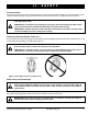
I I . S A F E T Y Weight Limitations Your power chair is rated for a maximum weight capacity. Please refer to the specifications table for this limit. WARNING! Exceeding the weight capacity voids your warranty and may result in personal injury and/or damage to your power chair. Pride will not be held responsible for injuries and/or property damage resulting from failure to observe weight limitations. WARNING! Do not carry passengers on your power chair.
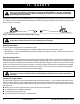
I I . S A F E T Y WARNING! Even though your power chair is capable of climbing slopes greater than those illustrated in figure 1, do not, under any circumstances, exceed the incline guidelines or any other specifications presented in this manual. Doing so could cause instability in your power chair, resulting in personal injury and/or damage to your power chair. In compliance with the Americans with DisabilitiesAct of 1990, all handicap public access ramps are required to have a maximum slope of 5°.
I I . S A F E T Y Freewheel Mode Your power chair is equipped with a manual freewheel lever to allow for manual maneuverability by a trained attendant. For more information about how to place your power chair into and out of freewheel mode, see IV. The Quantum Jazzy 1400 Series. WARNING! Do not use your power chair in freewheel mode without an attendant present. Personal injury may result. WARNING! Do not attempt to personally place your power chair in freewheel mode while seated on it.
I I . S A F E T Y Doors n Determine if the door opens toward or away from you. n Drive your power chair gently and slowly forward to push the door open. Or drive your power chair gently and slowly backward to pull the door open. Elevators Modern elevators have a door edge safety mechanism that, when pushed, reopens the elevator door(s).
I I . S A F E T Y Positioning Belts Your authorized Pride provider, therapist(s), and other healthcare professionals are responsible for determining your requirement for a positioning belt in order to operate your power chair safely. WARNING! If you require a positioning belt to safely operate your power chair, make sure it is fastened securely. Serious personal injury may result if you fall from the power chair. WARNING! The positioning belt is not designed for use as a seat belt in a motor vehicle.
I I . S A F E T Y Preventing Unintended movement WARNING! If you anticipate being seated in a stationary position for an extended period of time, turn off the power. This will prevent unexpected motion from inadvertent joystick contact. This will also eliminate the possibility of unintended chair movement from electromagnetic (EM) sources. Failure to do so may result in personal injury. Prescription Drugs/Physical Limitations Users must exercise care and common sense when operating a power chair.
I I I . E M I / R F I EMI/RFI Laboratory tests performed by the Food and Drug Administration (FDA) have shown that radio waves can cause unintended motion of power chairs. Radio waves are a form of electromagnetic energy. When this energy adversely affects the operation of an electronic device, it is called Electromagnetic Interference (EMI) or Radio Frequency Interference (RFI). WARNING! Radio waves may interfere with the control of power chairs.
I I I . E M I / R F I What is the FDA doing about the problem? The FDA has written to the manufacturers of power chairs and requested that they test their new products to be sure that they provide a reasonable degree of immunity against EMI/RFI. The letter states that power chairs should have an immunity of at least 20 V/m. This provides a reasonable degree of protection against the common sources of EMI/RFI.
I V. T H E Q U A N T U M J A Z Z Y 1 4 0 0 S E R I E S THE QUANTUM JAZZY 1400 SERIES The Quantum Jazzy has two main assemblies: the seat and the power base. See figures 2 and 3. Typically, the seat assembly includes the armrests, seatback, and seat base. The seat may also have some optional accessories attached to it, such as a basket, a cane/crutch holder, or a cup holder. See IX. Optional Accessories. The power base is the heart of the Power chair.
I V. T H E Q U A N T U M J A Z Z Y 1 4 0 0 S E R I E S SPECIFICATIONS Suspension: Active-Trac Suspension with Rear Suspension Drive Wheels: 1470/1420 - 16 in., pneumatic, center-mounted (solid tires are optional) 1400 - 14 in., pneumatic, center-mounted (solid tires are optional) Caster Wheels: 1470/1420 - 9 in., pneumatic, rear articulating (solid tires are optional) 1400 - 8 in., solid, rear articulating Anti-tip Wheels: 1470/1420 - 8 in., solid, front mounted 1400 - 6 in.
I V. T H E Q U A N T U M J A Z Z Y 1 4 0 0 S E R I E S ELECTRONICS TRAY REAR SEAT TOWER FREEWHEEL LEVER (UNDERNEATH ELECTRONICS TRAY) FRONT SEAT TOWER BATTERY BATTERY POWER MODULE ONBOARD BATTERY CHARGER (UNDERNEATH ELECTRONICS TRAY) FRONT SEAT TOWER REAR SEAT TOWER Figure 3. The Quantum Jazzy 1470 Power Base (Shroud Removed. 1420 and 1400 are similar.) ONBOARD CHARGER AC POWER CORD AMMETER MAIN CIRCUIT BREAKER CHARGER FUSE CONTROLLER CONNECTOR (REMOTE PLUS SHOWN) Figure 4.
I V. T H E Q U A N T U M J A Z Z Y 1 4 0 0 S E R I E S Electronics Tray The electronics tray is located on the back of the power base. See figures 3 and 4. The ammeter, the onboard charger AC power cord, the main circuit breaker, the controller connector, and the charger fuse are all located on the electronics tray. Ammeter: The ammeter displays the chargers current output in amps. See VI. Batteries and Charging.
I V. T H E Q U A N T U M J A Z Z Y 1 4 0 0 S E R I E S Manual Freewheel Lever For your convenience, your power chair is equipped with one of two manual freewheel levers. See figures 5, 5a, 6, and 6a. These levers allow you to disengage the drive motors and maneuver the chair manually. WARNING! Do not use your power chair while the drive motors are disengaged unless you are in the presence of an attendant! Do not disengage the drive motors when your power chair is on an incline.
V. C O M F O R T A D J U S T M E N T S COMFORT ADJUSTMENTS After becoming familiar with your power chairs operation, you may find the need to make some adjustments to increase your comfort, such as seat height and angle, armrest angle, footrest height and angle, and the controllers position. If your power chair is equipped with a Synergy Seat or the TRU-Balance, refer to the information provided in separate manuals.
V. C O M F O R T A D J U S T M E N T S Reclining Seat If your power chair is equipped with a reclining seat, you can adjust the seatback angle with the seatback release lever. The lever is located on the right side of the seat base. JAM NUT JAM NUT To adjust the seatback angle: 1. Press down on the lever. 2. Move the seatback to the desired position. 3. Release the lever.
V. C O M F O R T A D J U S T M E N T S BOLT, SPACERS, AND NUT SETSCREW Figure 10. Footrest Height Figure 11. Footrest Angle Footrest Angle You can adjust the angle of the footrest with a hex key. See figure 11. To adjust the footrest angle: 1. Turn the setscrew clockwise to raise the front of the footrest. 2. Turn the setscrew counterclockwise to lower the front of the footrest. SETSCREW Controller Position The controller can easily slide out away from the armrest, or in toward the armrest.
V. C O M F O R T A D J U S T M E N T S SFR RELEASE LEVER Figure 13. Swing-Away Footrests ELR RELEASE LEVER Figure 14. Elevating Leg Rests Swing-away Footrests Swing-away Footrests enable you to rotate the leg rests to the side before you transfer on or off your Quantum. To move the SFRs: 1. Push in the release lever. See figure 13. 2. Rotate the SFRs. To adjust the SFR length: 1. Remove the two screws from the side of each leg rest extension. See figure 15. 2.
V. C O M F O R T A D J U S T M E N T S Anti-Tip Wheels The anti-tip wheels are designed to give your power chair increased stability on rough surfaces. The anti-tip wheels are preset at the factory to a height of 1/2-in. off the ground. This setting is for smooth surfaces or indoor use only. If you plan on using your power chair on rough surfaces, it may be necessary to adjust the anti-tip wheels to better suit your needs.
V. C O M F O R T A D J U S T M E N T S Power Elevating Seat Option Your power chair may be equipped with a power elevating seat actuator. See figure 18. The power elevating seat is equipped with a system that reduces the power chairs speed by one half whenever the seat is elevated more than 1-2 inches.
V. C O M F O R T A D J U S T M E N T S NOTE: Be sure you are on a flat level surface before activating the power elevating seat. Power Elevating Seat Operation You can control the power seat through either the toggle switch located on the armrest or through your controller. For information on how to raise and lower your power seat through your controller, see VII. Operation. To operate the power elevating seat: 1. Push the toggle switch forward to raise the seat. See figure 19.
V I . BAT T E R I E S A N D C H A RG I N G BATTERIES AND CHARGING The Quantum Jazzy uses two long-lasting, 12-volt, deep-cycle batteries. These batteries are sealed and maintenance free. Since they are sealed, there is no need to check the electrolyte (fluid) level. Deep-cycle batteries are designed to handle a longer and deeper discharge. Though they are similar in appearance to automotive batteries, they are not interchangeable.
V I . BAT T E R I E S A N D C H A RG I N G Battery Break-in To break in new batteries for maximum efficiency: 1. Fully recharge any new battery prior to its initial use. This brings the battery up to about 90% of its peak performance level. 2. Operate your power chair throughout the house and yard. Move slowly at first, and dont stray too far until you become accustomed to the controls and break in the batteries. 3.
V I . BAT T E R I E S A N D C H A RG I N G How can I get maximum range or distance per charge? Rarely do you have an ideal driving situation such as smooth, flat, hard terrain with no wind, hills, or curves. More often you are presented with hills, sidewalk cracks, uneven and loosely packed surfaces, curves, and wind. All of these factors will affect the distance or running time per battery charge.
V I . BAT T E R I E S A N D C H A RG I N G NOTE: The useful life of a battery is quite often a reflection of the care it receives. How can I ensure maximum battery life? A fully charged deep-cycle battery will provide reliable performance and extended battery life. Keep your power chairs batteries fully charged whenever possible.
V I I . O P E R AT I O N REMOTE PLUS CONTROLLER The electronic controller is what you use to operate your power chair. It takes the battery voltage and sends it to the appropriate system. The electronic controller also enables you to monitor battery charge, electronic controller functions, and the condition of your electrical system. Also, it may be used to control some optional systems such as power elevating seats and lights. The Remote Plus is a modular electronic control system.
V I I . O P E R AT I O N WARNING! Unless faced with an emergency situation, do not use the on/off key to stop the chair. This will cause the power chair to stop abruptly. WARNING! Always turn the power off when you are stationary to prevent unexpected movement. Mode Key Press the key to change speed setting or to activate the power accessories. See Speed Settings or Power Accessories. Speed Setting Indicator Indicates the selected speed setting.
V I I . O P E R AT I O N NOTE: If you still get ripple up and down of lights, contact your authorized Pride provider. NOTE: When the batteries approach a discharged state, the first red light will begin to slowly flash, reminding you the batteries need to be charged immediately! Speed Settings The Remote Plus speed settings range from 1 to 5. Typically, the slowest speed setting is 1 and the fastest speed setting is 5. The settings are indicated by the number of lights that are lit.
V I I . O P E R AT I O N Actuator Lighting Module (Not Shown) The actuator lighting module is also located on the power base. The actuator lighting module provides a control and power interface between the power module, the lights, and/or the power seat actuator. Sleep Mode Your Remote Plus controller has a sleep mode feature. Sleep mode is a built-in circuit that automatically shuts off the main power if the joystick is not moved in any direction for a period of time.
V I I . O P E R AT I O N DX CONTROLLER The Dynamic DX electronic control system is a modular system. The electronics necessary to operate the power chair are contained in several modules located on different parts of your power chair.
V I I . O P E R AT I O N On/Off Key The on/off key toggles the system power on and off. WARNING! Unless faced with an emergency situation, do not use the on/off key to stop the chair. This will cause the power chair to stop abruptly. WARNING! Always turn the power off when you are stationary to prevent unexpected movement. NOTE: If the joystick is not in the neutral (center) position when you turn on the power, you may cause a fault in the system. See Out Of Neutral At Power Up.
V I I . O P E R AT I O N Drive Program Select Key The drive program select key enables you to select a drive program and an actuator mode. Your Dynamic DX controller was preprogrammed at the factory for five drive programs 1(slowest) to 5(fastest). The drive mode is indicated by a number in the center of the keypad. NOTE: The drive mode settings are preset at the factory. If your authorized Pride provider changes these settings, please make note of these changes. To change the drive mode program: 1.
V I I . O P E R AT I O N Fault Codes The system status LED is displayed within the on/off key. This LED is lit if the system is turned on. It also flashed in groups called flash codes, to indicate system faults. The table below identifies the individual fault codes. If your keypad displays one of these codes, contact your authorized Pride provider. FLASH CODE SEQUENCE DIAGNOSIS SOLUTION •—•—•— DX module fault See your authorized Pride provider.
V I I I . C A R E A N D M A I N T E NA N C E CARE AND MAINTENANCE Your Quantum Jazzy is a sophisticated power chair. Like any motorized vehicle, it requires routine maintenance checks. You can perform some of these checks, but others require assistance from an authorized Pride provider. Preventive maintenance is very important. If you follow the maintenance checks in this section as scheduled, you can help ensure that your power chair gives you years of trouble-free operation.
V I I I . C A R E A N D M A I N T E NA N C E n Use a rubber conditioner on the tire sidewalls to help preserve them. Check the tires for wear. WARNING! Never use a rubber conditioner on the tread area of the tires; doing so may make the tires slippery and cause your Jazzy to skid. n The body shroud has been sprayed with a clear sealant coating. You can apply a light coat of car wax to help it retain its high-gloss appearance. n Check all electrical connections.
V I I I . C A R E A N D M A I N T E NA N C E Monthly Checks n Check that the anti-tip wheels do not rub the ground when you operate the power chair. Adjust them as necessary. See V. ComfortAdjustments. n Check for extreme wear on the anti-tip wheels. Replace them as necessary. n Check for drive tire wear. See an authorized Pride provider for repair. n Check the caster wheels for wear. Replace them as necessary.
V I I I . 5. 6. 7. 8. 9. C A R E A N D M A I N T E NA N C E Pull the wheel off the axle. Remove the old tube from the pneumatic tire and replace it with a new tube. Slide the wheel back onto the shaft. Reinstall the drive wheel nut into the center hub and tighten. Inflate the pneumatic tire to 30 - 35 psi. Battery Replacement For battery specifications, see VI. Batteries and Charging. A diagram is printed on a decal located on the power chair frame near the battery tray. See figure 24.
V I I I . C A R E A N D M A I N T E NA N C E Motor Brushes The electric motors that power your power chair use carbon brushes. These brushes may become susceptible to wear over a long period of time. The motor brushes are the two contacts located inside the motor assembly that supply power to the motor. They are designed to provide several thousand hours of operation. However, if the brushes become dirty with carbon deposits or wear out, the motor will run poorly or not at all.
I X . O P T I O N AL AC C E S S O R I E S OPTIONAL ACCESSORIES The following accessories are available from your authorized Pride provider. Positioning Belt The positioning belt is designed to support your torso so that you do not slide down or forward in the seat. n The positioning belt is not designed for use as a restraining device. n Make sure the belt is secure but does not cause discomfort. WARNING! The positioning belt is not designed for use as a seat belt in a motor vehicle.
X .
NOTES 48 www.pridemobility.
Quality Control Checklist Thank you for making the Quantum Jazzy your choice in power chairs. We have thoroughly inspected your Quantum Jazzy. The following check marks indicate that it has been tested, driven, and inspected. Europa Controller Remote Plus Controller Joystick Serial # Controller Serial # 182 Susquehanna Ave. Exeter, PA 18643 1-800-800-8586 Controller Serial # Controller Serial # Quantum Hotline: 1-866-800-2002 www.quantumrehab.