Copyright Copyright © 2004 by Quantum Corporation. All rights reserved. Document Origination: Boulder, Colorado, USA. Trademarks Quantum, the Quantum logo, and the DLTtape logo are trademarks of Quantum Corporation, registered in the U.S.A. and other countries. DLTtape, DLTSage, Value DLTtape, and Super DLTtape are trademarks of Quantum Corporation. Other company and product names used in this document are trademarks, registered trademarks, or service marks of their respective owners.
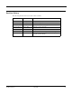
Revision History The following table lists all revisions made to this document.
Notes iv May 2004 001596-01 Rev A07
Table of Contents 1 Introduction . . . . . . . . . . . . . . . . . . . . . . . . . . . . . . . . . . . . . . . 1-1 Purpose and Scope. . . . . . . . . . . . . . . . . . . . . . . . . . . . . . . . . . . . . . . . . . . . . . . . . . . . . . . . . . . . . . . Related Documents . . . . . . . . . . . . . . . . . . . . . . . . . . . . . . . . . . . . . . . . . . . . . . . . . . . . . . . . . . . . . . Structure of this Manual . . . . . . . . . . . . . . . . . . . . . . . . . . . . . . . . . . . . . . . . . .
Table of Contents Setting the SCSI ID. . . . . . . . . . . . . . . . . . . . . . . . . . . . . . . . . . . . . . . . . . . . . . . . . . . . . . . . . . . 3-4 Connecting the Cables . . . . . . . . . . . . . . . . . . . . . . . . . . . . . . . . . . . . . . . . . . . . . . . . . . . . . . . . 3-5 Terminating Your Tabletop Tape Drive. . . . . . . . . . . . . . . . . . . . . . . . . . . . . . . . . . . . . . . . 3-8 Powering the Terminator . . . . . . . . . . . . . . . . . . . . . . . . . . . . . . . . . . .
List of Figures 3 DLT VS80 Installation . . . . . . . . . . . . . . . . . . . . . . . . . . . . . . . . 3-1 Figure 3-1. Tabletop Tape Drive Rear Panel Layout. . . . . . . . . . . . . . . . . . . . . . . . . . . . . . . . . . . . . 3-4 Figure 3-2. SCSI ID Selector Switch. . . . . . . . . . . . . . . . . . . . . . . . . . . . . . . . . . . . . . . . . . . . . . . . . 3-5 Figure 3-3. Tape Drive SCSI and Power Cable Connections . . . . . . . . . . . . . . . . . . . . . . . . . . . . . . 3-6 Figure 3-4.
List of Figures Notes viii May 2004 001596-01 Rev A07
List of Tables 3 DLT VS80 Installation . . . . . . . . . . . . . . . . . . . . . . . . . . . . . . . . 3-1 Table 3-1. Selecting the SCSI ID. . . . . . . . . . . . . . . . . . . . . . . . . . . . . . . . . . . . . . . . . . . . . . . . . . . 3-11 Table 3-2. Understanding Errors Indicated by Front Panel LEDs. . . . . . . . . . . . . . . . . . . . . . . . . . 3-20 4 DLT VS80 Use. . . . . . . . . . . . . . . . . . . . . . . . . . . . . . . . . . . . . . . 4-1 Table 4-1.
List of Tables Notes x May 2004 001596-01 Rev A07
C HAPTER 1 Introduction Chapter 1 1.1 Purpose and Scope This Installation and Operations Guide is a comprehensive source of information about the DLT VS80 tape drive (internal and tabletop). This manual provides all the information you need to install and use your internal tape drive or tabletop tape drive. 1.2 Related Documents DLT VS80 Tape Drive Product Specification (001597-01) DLT1/VS80 SCSI Interface Guide (000825-01) 1.
Chapter 1: Introduction 1.4 Conventions Used in this Manual This manual uses the following conventions: NOTE: Notes provide supplemental information. C AUTION 1.5 Cautions provide information you must know to avoid damaging the tape drive or losing data. For More Information The web site www.quantum.com includes valuable information about all Quantum products; or for personalized information about Quantum’s reliable data protection products, call 1-800-624-5545 in the U.S.A. and Canada. 1.
C HAPTER 2 Product Information Chapter 2 This chapter introduces the DLT VS80 tape drive and provides a general overview of the product. 2.1 DLT VS80 Tape Drive Overview Your Quantum DLT VS80 tape drive is a value-priced, high-reliability, high-capacity linear streaming data cartridge tape drive designed for use on entry- to mid-range computing platforms.
Chapter 2: Product Information 2.2.2 Capacity The tape drive uses DLTtape™ IV data cartridges, which offer 40 GB of native data storage or up to 80 GB of compressed data storage. The capacity you realize in practice depends on the data set. 2.2.3 Data Compression The tape drive includes a data compression feature that helps it store data efficiently. A read/write buffer of up to 2 MB provides working space for the compression feature, allowing you to get the most out of the available media space. 2.2.
C HAPTER 3 DLT VS80 Installation Chapter 3 This chapter explains how to configure and install your tabletop or internal tape drive. Follow the steps and instructions presented in this chapter to install and configure your tape drive. 3.1 Preparing to Install Your Tape Drive This section helps you prepare to install your tabletop tape drive or internal tape drive. 3.1.
Chapter 3: DLT VS80 Installation 3.1.2 Before You Begin Installing your DLT VS80 tabletop tape drive requires no special tools. You will need a ballpoint pen to change the SCSI ID switch on the rear panel of the tape drive. If you are installing a DLT VS80 internal tape drive, refer to “Installing Your Internal Tape Drive” on page 3-10 for instructions.
DLT VS80 Tape Drive Installation and Operations Guide 3. With the tape drive still in the shipping box, reach under and around the tape drive, carefully lift it out of the shipping box, and place it on the work surface, top facing up. Do not stand the tape drive on either end. 4. Carefully remove the tape drive from the protective bag. NOTE: Save the packing materials in case you need to move or ship your tape drive in the future.
Chapter 3: DLT VS80 Installation 3.2.2 Setting the SCSI ID All SCSI devices attached to the server or workstation must have a unique SCSI ID. Check the SCSI IDs on all other devices on the selected server or workstation, including the SCSI host bus adapter, and select an unused SCSI ID for your tape drive. The factory default SCSI ID for this tape drive is 5, as shown in Figure 3-1.
DLT VS80 Tape Drive Installation and Operations Guide To set the SCSI ID on the tabletop tape drive, use a small screwdriver or ballpoint pen to press the button above the SCSI ID display to select the next lower SCSI ID. Press the button below the SCSI ID display to select the next higher SCSI ID. Each time you press one of these buttons, the SCSI ID decreases or increases by one. Press the appropriate button until the desired SCSI ID appears on the switch display.
Chapter 3: DLT VS80 Installation 4. Connect one end of the SCSI cable to one of the connectors on the rear panel of your tape drive, as shown in Figure 3-3. Either SCSI connector works equally well. To next device To SCSI host bus adapter Figure 3-3. Tape Drive SCSI and Power Cable Connections NOTE: Figure 3-3 does not show a terminator because none of the three tape drives in the illustration are at the end of the SCSI bus.
DLT VS80 Tape Drive Installation and Operations Guide 5. Connect the other end of the SCSI cable to the connector on your SCSI host bus adapter, as shown in Figure 3-4 or to the connector on the previous SCSI device on the SCSI bus. Host bus adapter SCSI cable Figure 3-4. Workstation SCSI Cable Connections NOTE: If the SCSI cable does not fit the connector on the SCSI host bus adapter, you either have an incompatible SCSI host bus adapter or you need to purchase a cable adapter.
Chapter 3: DLT VS80 Installation Terminating Your Tabletop Tape Drive You must terminate the tape drive if it is the last physical device on the SCSI bus (at the end of the SCSI chain). If another SCSI device is the last device on the SCSI bus, confirm that it is properly terminated and do not terminate your tape drive. NOTE: Regardless of which device terminates the SCSI bus, it must have power applied and be powered on for proper termination to occur.
DLT VS80 Tape Drive Installation and Operations Guide 3.2.4 Completing the Installation 1. Secure all the SCSI cable connectors by tightening their screws until snug. 2. Make sure the power switch on the rear panel of the tabletop tape drive is in the OFF position. See Figure 3-1 for reference. 3. Attach the female connector on the power cable to the power connector on the rear panel of the tape drive. 4. Plug in the power cable to a nearby power outlet. 5.
Chapter 3: DLT VS80 Installation 3.3 Installing Your Internal Tape Drive This section contains step-by-step instructions for installing your DLT VS80 internal tape drive. Be sure to read through the entire section before beginning the installation. 3.3.1 Unpacking Your Internal Tape Drive First, clear a desk or table so that you can unpack your tape drive.
DLT VS80 Tape Drive Installation and Operations Guide 3.3.2 Configuring Your Internal Tape Drive The following sections explain how to configure your internal tape drive. Setting the SCSI ID All SCSI devices that are attached to the server or workstation must have a unique SCSI ID. Check the SCSI IDs on all other devices on the selected server or workstation, including the SCSI host bus adapter, and select an unused SCSI ID for your tape drive.
Chapter 3: DLT VS80 Installation Terminating Your Internal Tape Drive You must terminate the tape drive if: • • It is the only SCSI device—other than the SCSI host bus adapter—on the selected server or workstation’s SCSI bus. It is the last SCSI device on the selected server or workstation’s SCSI bus. To terminate the tape drive, insert an active low-voltage differential (LVD) or multimode LVD/SE terminator into the connector on one end of the SCSI ribbon cable as shown in Figure 3-7.
DLT VS80 Tape Drive Installation and Operations Guide NOTE: If the SCSI cable that came with the SCSI host bus adapter already has a terminator built into it, do not use another terminator. An example of such a cable is shown in Figure 3-8. Terminator SCSI cable (supplied with host bus adapter) Figure 3-8. SCSI Cable with Built-in Terminator 3.3.
Chapter 3: DLT VS80 Installation 3. Remove the cover from the server or workstation as described in the server’s or workstation’s manuals. See Figure 3-9 as an example. Figure 3-9. Remove the Workstation Cover (example shown) 4. Locate an available 5¼-inch drive bay and remove the front cover from the drive bay as described in the server or workstation’s manuals.
DLT VS80 Tape Drive Installation and Operations Guide 5. Slide your tape drive into the open drive bay as shown in Figure 3-10. Example of tower drive bay Example of 2U enclosure drive bay Figure 3-10. Tape Drive Installation in an Open Drive Bay NOTE: Install an LVD/SE SCSI host bus adapter in the selected server or workstation now, if necessary. For more information on SCSI host bus adapter requirements, see “SCSI Requirements” on page 3-1.
Chapter 3: DLT VS80 Installation 6. Select a SCSI cable with an open 68-pin, high-density connector. 7. Connect one end of the SCSI cable to the SCSI connector on the rear panel of your tape drive. The SCSI connectors are keyed, preventing improper connection. N OTES: 1 If the SCSI cable does not fit the connector on your SCSI host bus adapter, you either have an incompatible SCSI host bus adapter or you need to purchase a cable adapter.
DLT VS80 Tape Drive Installation and Operations Guide 10. Secure the tape drive with the mounting screws provided, either in the sides or bottom of the tape drive sled, as appropriate for the server or workstation chassis. See Figure 3-12. C AUTION Using a screw that is too short can result in inadequate clamping force. Using a screw that is too long can cause damage to the internal circuit cards. Please see the note following Figure 3-12 for guidance. Figure 3-12.
Chapter 3: DLT VS80 Installation To complete the installation, follow these steps: 1. Replace the cover on the server or workstation. 2. Attach the power cables to the server or workstation and all attached accessories. 3. Power on the server or workstation and allow its operating system to start. 4. Check your tape drive to make sure it is working properly by following the steps in “Testing Your Tape Drive.” 3.
DLT VS80 Tape Drive Installation and Operations Guide 3.5 Troubleshooting Your Tape Drive This section provides both general troubleshooting guidelines and an LED-specific problem/solution table to help you troubleshoot your tape drive. 3.5.1 General Troubleshooting Guidelines If you have a problem when using the tape drive, first try to isolate the cause of the problem.
Chapter 3: DLT VS80 Installation If the LEDs on the front panel act differently than described in “Testing Your Tape Drive” on page 3-18, the tape drive is not working properly. Table 3-2 helps you troubleshoot problems with the tape drive: Table 3-2. Understanding Errors Indicated by Front Panel LEDs Symptom Problem Solution None of the tape drive’s LEDs illuminate. The tape drive is not receiving power. Check the tape drive’s power cable.
DLT VS80 Tape Drive Installation and Operations Guide Table 3-2. Understanding Errors Indicated by Front Panel LEDs (Continued) Symptom Problem Solution The host server or workstation does not recognize the tape drive. (continued...) The SCSI bus might be improperly terminated. • If your tape drive is the last or only device on the SCSI bus, make sure the tape drive is properly terminated.
Chapter 3: DLT VS80 Installation Notes 3-22 May 2004 001596-01 Rev A07
C HAPTER 4 DLT VS80 Use Chapter 4 This chapter explains how to use your DLT VS80 tape drive. It describes the front panel LEDs and controls, how to load and eject DLTtape IV data cartridges, how to use and care for DLTtape IV data cartridges, and how to use the cleaning cartridge. NOTE: For current information on operating system, application, and tape driver compatibility, visit: www.quantum.com 4.
Chapter 4: DLT VS80 Use 4.1.1 Indicator Activity During Power-On Self-Test (POST) Every time you power on your tape drive, it conducts a power-on self-test (POST). This test ensures that your tape drive is working properly and is ready to use. While POST is in progress, watch the front panel LEDs. 1. The LEDs illuminate all at once and then turn off. 2. The Ready (green) LED blinks during initialization and remains illuminated after POST. 3.
DLT VS80 Tape Drive Installation and Operations Guide Table 4-2 describes what each front panel indicator means. Table 4-2. Indicator Activity Indicator State Operating Condition Drive Error (amber) Blinking An unrecoverable tape drive error or a POST error has occurred— call Technical Support. Off No tape drive Errors. On Power to the tape drive. Off No power to the tape drive. Blinking (constant period & duty cycle) Tape is in motion. Blinking (dual period & duty cycle) Reserved.
Chapter 4: DLT VS80 Use 4.2 Data Cartridge Use and Care Your tape drive uses only DLTtape IV data cartridges. Your tape drive can read—but not write to— DLTtape IV data cartridges previously written in the DLT 4000 format. NOTE: Your tape drive automatically unloads any other data cartridge types and any data cartridges whose format it cannot read. Make sure all data cartridges that you use for writing are either unformatted or have been used with your tape drive before loading them. 4.2.
DLT VS80 Tape Drive Installation and Operations Guide 4.2.2 Unloading a Data Cartridge C AUTION Remove the data cartridge from your tape drive before powering off the tabletop tape drive or the host server or workstation for an internal tape drive. Leaving a data cartridge in the tape drive when power is off can result in data cartridge and tape drive damage and may cause data loss because the header/catalog data may not be properly written before the tape drive loses power.
Chapter 4: DLT VS80 Use 4.2.3 Write-Protecting Data Cartridges All DLTtape IV data cartridges have a write-protect switch to prevent accidental erasure of data. Before loading a DLTtape IV data cartridge into your tape drive, make sure the write-protect switch on the front of the data cartridge is in the position you need. Orange indicator Write-protect switch Write-protected Write-enabled Figure 4-4.
DLT VS80 Tape Drive Installation and Operations Guide 4.2.4 Caring for Your Data Cartridges To ensure the longest possible life for all of your DLTtape IV data cartridges, follow these guidelines: • Do not drop or strike a data cartridge. Excessive shock can displace the tape leader, making the data cartridge unusable and possibly damaging your tape drive. • Store your DLTtape IV data cartridges in their storage cases.
Chapter 4: DLT VS80 Use 4.2.5 Using the Cleaning Cartridge When the Clean/Media LED is illuminated, your tape drive’s read/write head may need to be cleaned. Follow the instructions on page 4-4 to load the cleaning cartridge. Cleaning typically takes several minutes, during which the Ready LED blinks. C AUTION Use only Quantum-approved cleaning cartridges in your tape drive. Use of any other type of cleaning cartridge can damage the read/write head in your tape drive.
C HAPTER 5 Chapter 5 DLT VS80 Firmware This chapter explains how to update your tape drive’s firmware from a DLTtape IV data cartridge or from a file on the host server or workstation. 5.1 Updating Tape Drive Firmware—Overview The DLT VS80 automatically updates the tape drive’s firmware directly from a DLTtape IV data cartridge containing the appropriate information. The tape drive also updates the tape drive’s firmware from the host server or workstation.
Chapter 5: DLT VS80 Firmware 5.2 Creating a Firmware Update Data Cartridge To perform the firmware update, you need a DLTtape IV data cartridge and a copy of the firmware image. This image must be byte-written without compression onto the media. You must copy the firmware image to the media instead of using a backup utility to transfer it to the tape. NOTE: UNIX Systems: You can use the FTP utility to transfer the binary image file onto the UNIX system.
DLT VS80 Tape Drive Installation and Operations Guide 3. Press and hold the Unload button on the tape drive’s front panel until the LEDs are no longer illuminated (approximately 12 seconds), then release the Unload button. The Ready LED flashes. 4. Within four seconds, press and release the Unload button again. All LEDs should blink, indicating that the tape drive is in firmware upgrade mode.
Chapter 5: DLT VS80 Firmware 5.3.2 Troubleshooting the Firmware Upgrade If the firmware upgrade failed, the tape drive does not unload the Firmware Upgrade Data Cartridge at the end of the process. Refer to Table 5-1 for troubleshooting information. Table 5-1. Firmware Upgrade Troubleshooting Problem Indications/Solution The data cartridge is not a valid Firmware Upgrade Data Cartridge. Indications: The tape drive does not attempt to update the firmware.
4001 Discovery Dr., Ste. 1100 Boulder, CO 80303 720.406.