
Installation Instructions
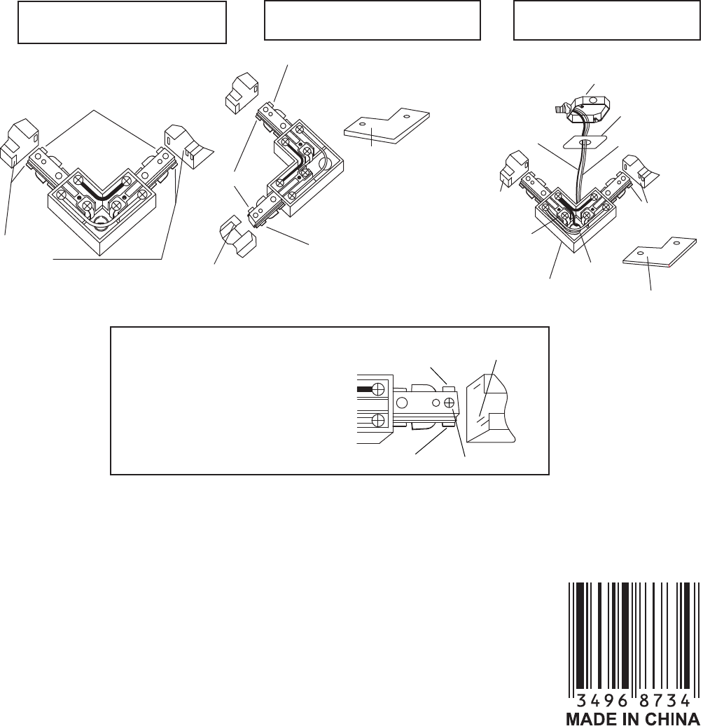
L CONNECTOR
RIGHT TURN LAYOUT
LOOKING UP AT CEILING
Break off
the ground
tab on this side
Ground
conductor
Ground
conductor
WARNING: If improper
ground tab has been
removed, DO NOT USE
connector since
grounding will not be
maintained.
Ground
tab
Break off
the ground
tab on this side
Remove cover
plate to make
connections
(Hot) Black
Ceiling plate
White
(Neutral)
Ground
conductor
Opening
Ground
conductor
Green ground
terminal screws
Discard "L" shaped
steel plate on bottom
Remove cover
plate to make
connections
Break off
the ground
tab on this side
Outlet box
LEFT TURN LAYOUT
LOOKING UP AT CEILING
ELECTRICAL FEEDING
THRU CDNNECTOR
Connector
Set screw
Track
Ground
conductor
Remove this tab
Ground tab
1. Remove plastic cover plate to expose terminal screws.
2. Open the round hole on back side of the connector as well.
3. Loosen set screws. Slide Connector and plate assembly into
open end of Track, tighten screws, and install Track to ceiling.
4. To maintain circuit polarity, ground tabs on connectors must
be properly prepared. With pliers, break off the tab on
NON-GROUND conductor side of the track section you are joining.
5. Pull two wires from outlet box through open hole in Connector
and plate assembly as shown.(If green ground wire is available,
it must be attached to green ground screw.)
6. Cut and strip wires from outlet box and fasten to screw terminals.
Attach black outlet box wire to brass (gold) screw. Attach white
wire to nickel (silver) screw. Tighten screws. Push excess wires
back into outlet box.
7. Replace cover on Connector and tighten screw.