
User Manual


LEA-6 - Data Sheet
GPS.G6-HW-09004-E2 Page 15 of 26
3 Electrical specifications
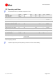
3.1 Absolute maximum ratings
Parameter Symbol Condition Min Max Units
Power supply voltage VCC -0.5 3.6 V
Backup battery voltage V_BCKP -0.5 3.6 V
USB supply voltage VDDUSB -0.5 3.6 V
Input pin voltage Vin -0.5 3.6 V
Vin_usb -0.5 VDDUSB V
DC current trough any digital I/O pin (except supplies) Ipin 10 mA
VCC_RF output current ICC_RF 100 mA
Input power at RF_IN Prfin
source impedance = 50 Ω,
continuous wave
15 dBm
Antenna bias voltage V_ANT 6 V
Antenna bias current I_ANT 100 mA
Storage temperature Tstg -40 85 °C
Table 11: Absolute maximum ratings
GPS receivers are Electrostatic Sensitive Devices (ESD) and require special precautions when
handling. For more information see section 6.4.
Stressing the device beyond the “Absolute Maximum Ratings” may cause permanent damage.
These are stress ratings only. The product is not protected against overvoltage or reversed
voltages. If necessary, voltage spikes exceeding the power supply voltage specification, given in
table above, must be limited to values within the specified boundaries by using appropriate
protection diodes. For more information see the LEA-6/ NEO-6/ MAX-6 Hardware Integration
Manual [1].