
Installation guide


Quasar CM-4251 Series User and Installation Guide
6
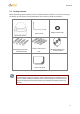
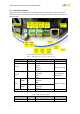
3.2 Camera Connections
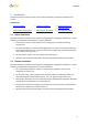
Figure 4 shows the various connectors and Reset button contained within the housing of the
CM-4251-xx camera. The connectors, pin numbers and signal definitions related to each pin are
listed in Table 2.
Figure 4: CM-4251 Camera Input/Output Connections
Table 2: CM-4251 Camera Connector Designations
Connector
Pin No.
Definition
Remarks
BNC
N/A
Analog Video Output
Alarm I/O
1
2
3
4
GND (Input-)
Input+
Output-
Output+
Alarm connection
Audio I/O
1
2
3
4
Output (L)
Output (R)
GND
Input
Two-way audio
transmission
Power
12VDC
1
2
3
Power
Reserved
GND
Power connection
24VAC
1
2
3
Power-1
Earth GND
Power-2
RJ45
N/A
10/100 Mbps Ethernet/PoE
Table 3: CM-4251 Camera Reset
Switch
Pin No.
Definition
Remarks
Reset Button
N/A
Restores to factory default