
Installation guide


Installation
17
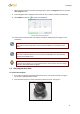
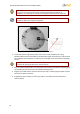
4. Snap the camera module back on the base plate with the wiring threaded through the gap at
the module base and then screw in the module-fastening screw.
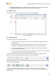
Figure 15: Replacing Camera Module onto Base Plate
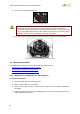
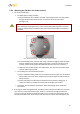
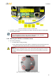
5. Plug the Cat 5 cable into the camera Ethernet port and, if needed, plug the power terminal
block into the power terminals.
6. If applicable, wire the Alarm In, Alarm Out, Audio In, and Audio-Out terminal blocks to
external devices.
Figure 16: Reset Button and Input/Output Connections
7. If needed, connect the other end of the Cat 5 cable to the network and turn on the power
from the power supply.
Note:
Do not reassemble the camera’s inner cover and Mini-Dome cover until after
hardware configurations and lens adjustments are made.