ORDER NO. MTNC010306C1 B5 Service Manual Color Television Main Manual (NA7D) Panasonic Models Chassis CT-27G6E/DE/UE CT-25G6E CT-25G6CE CT-25G6UE CT-27G6E CT-27G6DE CT-27G6UE AP361 AP361 AP361 AP362 AP362 AP362 Quasar Models SP-2724E SP-2724UE Chassis EC363 EC363 SP-2724E/UE This Service manual is issued as a service guide for the models of the NA7D family listed above. Included are schematics, alignment procedures, disassembly procedures, and a parts list.
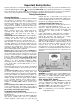
Important Safety Notice Special components are used in this television set which are important for safety. These parts are identified on the schematic diagram by the symbol and printed in BOLD TYPE on the replacement part list. It is essential that these critical parts are replaced with the manufacturer’s specified replacement part to prevent X-ray radiation, shock, fire or other hazards. Do not modify the original design without the manufacturer’s permission.
Service Adjustments (Electronic Control). . . . . . . . . . . . . . . . . . 22 Important Safety Notice . . . . . . . . . . . . . . . . . . 2 Safety Precautions . . . . . . . . . . . . . . . . . 2 Sub-Contrast. . . . . . . . . . . . . . . . . . . . . Sub-Brightness . . . . . . . . . . . . . . . . . . . Tint/Color Adjustment . . . . . . . . . . . . . . White Balance. . . . . . . . . . . . . . . . . . . . Sub-Brightness Final Adjustment . . . . . Horizontal Centering . . . . . . . . . . . . . . .
Service Notes Note: Some components may be affixed with glue. Be careful not to break or damage foil under the component or at the pins of the ICs when removing. Usually applying heat to the component for a short time while twisting with tweezers will break the component loose. Leadless Chip Component How to Replace Flat-IC (surface mount) - Required Tools - Chip components must be replaced with identical chips due to critical foil track spacing.
X-Ray Protection Circuit Check & Adjustments IMPORTANT: To protect against possible damage to the solid state devices due to arcing or static discharge, make certain that all ground wires and CRT DAG wire are securely connected. This test must be performed as final check before the Receiver is returned to the customer. If voltages are out of tolerance, immediate service and correction is required to insure safe operation and to prevent the possibility of premature component failure.
Receiver Feature Table FEATURE\MODEL CT-25G6E/CE/UE CT-27G6E/DE/UE SP-2724E/UE AP361 AP362 EC363 Tuning system 40K 40K 40K # of channels 181 181 181 Menu language Eng/Span/Fr Eng/Span/Fr Eng/Span/Fr Closed Caption X X X V-Chip X X X 75 Ω input X X X FM radio X N/A N/A EUR501455 EUR501450 EUR511514 A63QDB891X A68QDN891X M68LGL061X X X X 2 Line Digital 2 Line Digital 2 Line Digital V/A norm V V V MTS/SAP/DBX X X X AI Sound X X X 1.5W x 2 (10%) 1.
Location of Receiver Controls 1 2 3 4 5 Remote Control Sensor Front A/V Input (Available on some models) Figure 2. Location of Controls (Quasar models displayed, Panasonic models vary). Quick Reference Control Operation 1 Power Button - Press to turn ON or OFF. 2 Volume Buttons - Press to adjust Sound Level, or to adjust Audio Menus, Video Menus, and select operating features when menus are displayed 3 Channel Buttons - Press to select programmed channels.
Location of Controls POWER TV, VCR, DBS/CBL, DVD Press to turn ON and OFF. Press to select remote operation. TV/VIDEO EXIT/GUIDE Press to select TV or Video Mode. DBS function buttons. VOL CH Press to adjust TV sound and navigate in menus. Press to select next channel and navigate in menus. MUTE ACTION Press to mute sound. Press to access and cancel (CC) Closed Caption. Press to access menus. RECALL Press to display time, channel, sleep timer, and other options.
Disassembly for Service Back Cover Remove all the screws marked with an arrow( from the back of the Receiver. Note: • • • • • Disassembly for CRT Replacement 1. Discharge the CRT as instructed in the Safety Precautions (see page 2). 2. Disconnect the yoke (DY) plug, degaussing coil (DEG) plug from the main board. 3. Unplug the CRT 2nd anode button from the main board. 4. Remove the C-Board from the CRT base and unplug the black wire (CRT dag ground) C10. 5.
Chassis Service Adjustment Procedures All service adjustments are factory preset and should not require adjustment unless controls and/or associated components are replaced. Note: Connect the (-) lead of the voltmeter to the appropriate ground. Use IC801’s heat sink when the HOT ground symbol ( ) is used. Otherwise, use COLD ground ( ) — Tuner shield, IC451’s heat sink or FA2. Figure 4.
Purity and Convergence Procedure Adjustment is necessary only if the CRT or the deflection yoke is replaced or if the setting was disturbed. The complete procedure consists of: 1. Vertical Raster Shift Adjustment. (Only for Models with Purity/Convergence Assembly with 4 Pairs of Rings). 2. Initial static convergence. 3. Setting the purity. 4. Final static convergence. results, note part number and look for specifications at Service Center) When the CRT or the Yoke is Replaced Figure 8.
Purity Adjustment When the Receiver is in the Service Mode for making electronic adjustments, press the Recall button on the Remote Control to enter Purity Check. (See the Service Adjustments Electronic Controls procedure). Operate the Receiver for 60 minutes using the first Purity Check field (white screen) to stabilize the CRT. Fully degauss the Receiver by using an external degaussing coil. Press the Recall button on the Remote Control again until the Purity Check (green screen) appears.
Figure 11. Vertical Yoke Movement Figure 12. Horizontal Yoke Movement Figure 13. Convergence Magnets and Wedges Location Note: For models using 4 pairs of rings assemblies see Fig.
Service Mode (Electronic Controls) This Receiver has electronic technology using the I²C Bus Concept. It performs as a control function and it replaces many mechanical controls. Instead of adjusting mechanical controls individually, many of the control functions are now performed by using “On Screen Display Menu”. (The Service Adjustment Mode.
Press the POWER Button on the Remote Control to select the Service Adjustment. For Adjustments: 1.Press Channel Up/Down on the Note: Remote Control to select one of the available Service Adjustments (a in Fig. 14). Write Down the original value set (b in Fig. 14) for each address before modifying anything. It is easy to erroneously adjust the wrong item.
Cut-Off Adjustment CH C15 ACL-COEF-factory preset 94 C16 ACL-COEF-factory preset 80 C17 ACL-WAIT-factory preset 2 C18 ACL-THRESHOLD-factory preset 9 C19 MACROVISION-factory preset 3 C1A OSD SELECT-factory preset 1 C1B KILLER ON-factory preset 6 C1C KILLER OFF-factory preset 20 C1D KILLER TIME-factory preset 3 C1E ACC THRESHOLD-factory preset 17 C1F ACC OFF-factory preset 7 C20 MUTE TIME-factory preset 11 MTS Adjustment CH INPUT 33 M1 HIGH-LEVEL SEPARATION 25 M2
VCJ Adjustment (Continued) CH SF ACC AMP ON-factory preset 20 S10 ACC AMP CTL-factory preset 3 S11 BGP POSITION-factory preset 21 S12 OSD R-factory preset 30 S13 OSD G-factory preset 30 S14 OSD B-factory preset 30 S15 NOISE KILLER TIME-factory preset 5 S16 NOISE KILLER (ACC)-factory preset 50 S17 HV TIMING-factory preset 2 VCJ Adjustment (Black Expansion) CH Default Level CH Default Level P0 FORCE BS-factory preset 1 P1 DET ON/OFF-factory preset 1 P2 ROM SEL-factory
Other Adjustment CH Default Level (Without FM) Default Level (With FM) X0 AFCT 60 83 X1 AFCB 29 44 X2 AFCC 42 64 X3 CLOCK 128 128 CH TO B ITEMS PW To Check Purity: When Receiver is in Service Mode (red “CHK” is displayed), place a jumper in the AG connector between the terminals (shorting FB signal to ground). Press the Recall Button on the Remote Control to enter the White Purity Field Check Mode.
Notes: - 19 -
Instructional Flow Chart for Service Mode IMPORTANT Always Exit the Service Mode Following Adjustments. NORMAL MODE Momentarily short FA1 to FA2 ( ). AGING MODE • • • WHITE SCREEN Yellow “CHK” appears in upper left corner of screen. Volume Up/Down operate rapidly. Custumer Controls are set to nominal level. Place jumper across terminals on AG Connector RECALL QUICK ENTRY TO SERVICE MODE (ON REMOTE) N EXIT Adj. needed? • • • • • Select CABLE Mode. Set SLEEP time for 30, 60 or 90 Min.
A CUT-OFF ADJUSTMENTS. C ITEMS. CH ON REMOTE CONTROL TO SELECT ADJUSTMENT VOL VOL Y Adj. needed? ON REMOTE TO ADJUST THE LEVEL N POWER (ON REMOTE) M, S, P & X Adjustments procedures are similar to the B Adjustments. CH ON REMOTE CONTROL TO SELECT ADJUSTMENT VOL VOL Y Adj. N needed? ON REMOTE TO ADJUST THE LEVEL B POWER (ON REMOTE) N C EXIT Press Action and Power on the Receiver simultaneously for at least 2 seconds. Note: IMPORTANT Always Exit the Service Mode Following Adjustments.
Service Adjustments (Electronic Controls) Note: It is recommended to allow for a 30 minute warm up period, at high brightness level (use white screen), prior to any picture adjustment. Sub-Contrast Service DAC Adjustment (B3) This adjustment is factory set. Do not adjust unless repairs are made to associated circuit, the CRT Board or when the CRT is replaced. Preparation: 1. Apply a color bar signal pattern with 87.5% modulation, 70% saturated color bar with a 100 IRE white and 7.5 black.
• C5: Drive_B . . . . . .80 3. Confirm using Black & White pattern and a white screen the color balance (gray scale and white balance). If white balance is required perform the following: Procedure (Low Lights): 1. Apply a Black & White pattern. 2. Connect a jumper from the base of Q452 to cold ground ( ) (or apply +2.5V DC to TP1 to defeat the neck protector circuit). 3. Set the Red and Blue Cut-Off registers (C0 and C2) to 00. 4. On the Remote Control, press R-Tune to get a green horizontal line. 5.
Audio: 300Hz, 100% modulation, monaural (70 ±5dB, 75Ω OPEN, P/S 10dB). 2. Adjust the MTS Input Level Adjustment (M0) until the voltage measured is 106 ± 6.0mV rms. Stereo Separation Adjustment (M1 & M2) Figure 23. Horizontal Centering Vertical Size Service DAC Adjustment (C6) Preparation: Connect a monoscope pattern. Procedure: 1. In the Service Mode, select the Vertical Size Adjustment DAC (C6).
Service Adjustments (Mechanical Controls) Focus (part of T551) Preparation: Connect a Signal generator and select a dot pattern. Procedure: Adjust the FOCUS control VR to obtain the sharpest and clearest dot pattern. a. Adjust for best center. b. Adjust for best area between the center and top right corner.
Identification of Components Screw Screw Screw Screw Screw Screw Screw Screw Figure 26. Back Cover Removal (CT-25G6E/CE/UE & CT-27G6/DE/UE) Screw Screw Screw Screw Screw Screw Screw Screw Figure 27.
CRT (secured to cabinet by 4 screws on corners of CRT) Anode (high voltage) Yoke C board DAG ground Degaussing coil Speaker (4 screws) Speaker (4 screws) Tuner A/V jacks Flyback (T551) Note: After servicing the Receiver, dress cables and wires as indicated. Figure 28. Rear View Q351 R Out Q352 G Out CRT Socket Q353 B Out Figure 29.
IC050 Halftone IC001 MPU Components on trace side IC002 EEPROM IC003 Remote Sensor Front A/V Jacks IC451 Vertical Out IC005 3.3 V IC551 9V Reg IC2301 IC552 Right 5V Reg Audio Amp TNR001 Tuner D801 Rect Bridge Q501 H-Drive Q551 H-Out S-VHS IC2302 Left Audio Amp IC801 VCO A/V Jacks IC2201, MTS IC3101, AV SW on trace side RL801 Relay Flyback F801 T551 Fuse Figure 30.
C-BOARD -- TARJETA C C-BOARD SCHEMATIC, LAYOUT & VOLTAGES -- DIAGRAMA ELÉCTRICO, CIRCUITO IMPRESO Y VOLTAJES TARJETA C ALL MODELS -- TODOS LOS MODELOS Notes: • Check Parts List for most recent component values and part numbers. • Obtain voltages with a digital multimeter. • The board layouts were modified to enhance and display traces otherwise hidden by a mask.
A-BOARD -- TARJETA A CT-25G6E/CE/UE A-BOARD SCHEMATIC LEFT PORTION -- DIAGRAMA ELÉCTRICO TARJETA A SECCIÓN IZQUIERDA - 40 -
A-BOARD SCHEMATIC RIGHT PORTION -- DIAGRAMA ELÉCTRICO TARJETA A SECCIÓN DERECHA A-BOARD -- TARJETA A CT-25G6E/CE/UE CHIP TRANSISTOR LEAD DESIGNATION B E C IDENTIFICACIÓN DE TERMINALES PARA TRANSISTORES EN CHIP B E - 41 - C
A-BOARD - TARJETA A CT-27G6E/CE/UE & SP2724E/UE A-BOARD SCHEMATIC LEFT PORTION -- DIAGRAMA ELÉCTRICO TARJETA A SECCIÓN IZQUIERDA - 42 -
A-BOARD SCHEMATIC RIGHT PORTION -- DIAGRAMA ELÉCTRICO TARJETA A SECCIÓN DERECHA A-BOARD -- TARJETA A CT-27G6E/CE/UE & SP2724E/UE CHIP TRANSISTOR LEAD DESIGNATION B E C IDENTIFICACIÓN DE TERMINALES PARA TRANSISTORES EN CHIP B E - 43 - C
A-BOARD -- TARJETA A ALL MODELS -- TODOS LOS MODELOS A-BOARD VOLTAGES -- VOLTAJES TARJETA A IC001 1 2 3 4 5 6 7 8 9 10 11 12 13 14 15 16 17 18 19 20 21 22 23 24 25 26 27 28 29 30 31 32 33 34 35 36 37 38 39 40 . . . . . .GND . . . . . .1.39 . . . . . .4.98 . . . . . .4.91 . . . . . .2.47 . . . . . .4.95 . . . . . .2.43 . . . . . .4.99 . . . . . .2.36 . . . . . .2.90 . . . . . .4.95 . . . . . .GND . . . . . .2.47 . . . . . .4.97 . . . . . n.c . . . . . .4.98 . . . . . .2.93 . . . . . .1.35 . . . . . .3.
WAVEFORMS -- FORMAS DE ONDA ALL MODELS - TODOS LOS MODELOS A-BOARD WAVEFORMS -- FORMAS DE ONDA TARJETA A dos All Models los Modelos -- ToCHIP TRANSISTOR LEAD DESIGNATION B E 1 * 2 1.3V p-p [20µs] TPA5 (VIDEO) 5 1.0V p-p [20µs] IC001 PIN 22 (Y IN) 6 1.7V p-p [20µs] (R OUT) A11-1 1.4V p-p [20µs] (G OUT) A11-2 9 1.3V p-p [5ms] 13 IC451 PIN 7 (DRIVE) 48.0V p-p [5ms] 10 IC451 PIN 12 (VERT OUT) 14 3.1V p-p [20µs] IC001 PIN 43 (FB PULSE) 17 C 2.9V p-p [5µs] IC801 PIN 5 164.
A & C-BOARDS -- TARJETAS A Y C ALL MODELS - TODOS LOS MODELOS A & C-BOARDS LAYOUT -- CIRCUITO IMPRESO DE LAS TARJETAS A Y C - 46 -
SERVICE MODE (ELECTRONIC CONTROL) SERVICE ADJUSTMENT VALUES Model _____________________________________________ Ser #_____________ Date_________________ Note: Record the original settings PRIOR to modifying the registers. Mode Service Adjustment Adjustment Range Def. Val. Original Value New Value Mode Service Adjustment Adjustment Range Def. Val. Original Value New Value Cut-Off Adjustments, Cont.
SERVICE MODE, CONT. (ELECTRONIC CONTROL) SERVICE ADJUSTMENT VALUES Model _____________________________________________ Ser #_____________ Date_________________ Note: Record the original settings PRIOR to modifying the registers. Mode Service Adjustment Adjustment Range Def. Val. Original Value New Value Mode Service Adjustment Adjustment Range Def. Val. Original Value New Value VCJ Adjustments, Cont. (Black Expansion) Options Adjustments (Cont.
Schematic Notes IMPORTANT SAFETY NOTICE THIS SCHEMATIC DIAGRAM INCORPORATES SPECIAL FEATURES THAT ARE IMPORTANT FOR PROTECTION FROM X-RADIATION, FIRE AND ELECTRICAL SHOCK HAZARDS. WHEN SERVICING IT IS ESSENTIAL THAT ONLY MANUFACTURERS SPECIFIED PARTS BE USED FOR THE CRITICAL COMPONENTS DESIGNATED WITH A IN THE SCHEMATIC. CHIP TRANSISTOR LEAD DESIGNATION B E C SCHEMATIC NOTES 1. Resistors are carbon 1/4W unless noted otherwise. 2. Capacitors are ceramic 50V unless noted otherwise. 3.
Schematic Notes NOTA DE SEGURIDAD LOS DIAGRAMAS ELÉCTRICOS INCLUYEN CARACTERÍSTICAS ESPECIALES MUY IMPORTANTES PARA LA PROTECCIÓN CONTRA RAYOS-X, QUEMADURAS Y DESCARGAS ELÉCTRICAS. CUANDO SE DE SERVICIO ES IMPORTANTE USAR PARA REEMPLAZO DE COMPONENTES CRITICOS, SOLO PARTES ESPECIFICADAS POR EL FABRICANTES. LOS COMPONENTES CRITICOS ESTAN SEÑALADOS EN LOS DIAGRAMAS POR EL SIMBOLO . IDENTIFICACIÓN DE TERMINALES PARA TRANSISTORES EN CHIP B E C NOTAS DE LOS DIAGRAMAS 1.
Schematic Notes PARTS LIST NOTES: - 38 -
REPLACEMENT PARTS LIST Models: CT-25G6E/CE/UE, CT-27G6E/DE/UE & SP-2724E/UE Important Safety Notice: Components printed in BOLD TYPE have special characteristics important for safety. When replacing any of these components use only manufacturer’s specified parts. PART NO. REF NO. DESCRIPTION CAPACITORS PART NO. DESCRIPTION C362 ECJ2VC1H151J CAP,C 150PF-J-50V ECJ2VC1H151J CAP,C 150PF-J-50V C001 ECJ2VF1H103Z CAP,C .
REPLACEMENT PARTS LIST Models: CT-25G6E/CE/UE, CT-27G6E/DE/UE & SP-2724E/UE Important Safety Notice: Components printed in BOLD TYPE have special characteristics important for safety. When replacing any of these components use only manufacturer’s specified parts. REF NO. PART NO. DESCRIPTION REF NO. PART NO. DESCRIPTION C575 ECA0JM222B CAP,E 2200UF-6.3V C2320 ECA1CM100B C577 ECA1CM101B CAP,E 100UF/16V C2330 ECA1CM100B CAP,E 10UF-16V C578 ECA0JM332B CAP,E 3300PF-6.
REPLACEMENT PARTS LIST Models: CT-25G6E/CE/UE, CT-27G6E/DE/UE & SP-2724E/UE Important Safety Notice: Components printed in BOLD TYPE have special characteristics important for safety. When replacing any of these components use only manufacturer’s specified parts. REF NO. PART NO. DESCRIPTION D3004 MA3110MTX DIODE, ZENER D3005 MA3110MTX DIODE, ZENER D3006 MA3110MTX D3017 MA3110MTX REF NO. PART NO.
REPLACEMENT PARTS LIST Models: CT-25G6E/CE/UE, CT-27G6E/DE/UE & SP-2724E/UE Important Safety Notice: Components printed in BOLD TYPE have special characteristics important for safety. When replacing any of these components use only manufacturer’s specified parts. REF NO. Q3194 PART NO. 2SD601ARTX DESCRIPTION TRANSISTOR REF NO. SP-2724E/UE RELAYS RL801 TSEH0005 R001 ERJ6GEYJ102V RELAY PART NO.
REPLACEMENT PARTS LIST Models: CT-25G6E/CE/UE, CT-27G6E/DE/UE & SP-2724E/UE Important Safety Notice: Components printed in BOLD TYPE have special characteristics important for safety. When replacing any of these components use only manufacturer’s specified parts. R457 PART NO. ERJ6GEYJ122V R457 ERJ6GEYJ152V R458 ERJ6GEYJ273V DESCRIPTION REF NO. RES,M 1.2K-J-1/10W CT-25G6E/CE/UE PART NO.
REPLACEMENT PARTS LIST Models: CT-25G6E/CE/UE, CT-27G6E/DE/UE & SP-2724E/UE Important Safety Notice: Components printed in BOLD TYPE have special characteristics important for safety. When replacing any of these components use only manufacturer’s specified parts. REF NO. PART NO. DESCRIPTION REF NO. PART NO.
REPLACEMENT PARTS LIST Models: CT-25G6E/CE/UE, CT-27G6E/DE/UE & SP-2724E/UE Important Safety Notice: Components printed in BOLD TYPE have special characteristics important for safety. When replacing any of these components use only manufacturer’s specified parts. REF NO. PART NO. DESCRIPTION REF NO. PART NO.