
Service manual


- 27 -
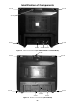
Figure 28. Rear View
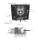
Figure 29. C-Board component locations
CRT (secured to cabinet by 4
screws on corners of CRT)
DAG ground
Anode (high voltage)
C board
Tuner
A/V jacks
Flyback (T551)
Note:
After servicing the
Receiver, dress cables and
wires as indicated.
Yoke
Speaker (4 screws)
Speaker (4 screws)
Degaussing coil
CRT Socket
Q351
R Out
Q352
G Out
Q353
B Out