Room Air Conditioner INSTALLATION AND OPERATING INSTRUCTIONS Model : HQ-2081TH Please read these operating instructions thoroughly before using your air conditioner and keep for future reference. For assistance, please call : 1-800-211-PANA(7262) or Register your product at : http://www.panasonic.
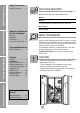
Safety Precautions Safety Precautions Safety Precautions .............3 FOR YOUR RECORDS Staple your receipt to this page in case you need it later. Write down the model and serial numbers here: Model # Serial # You can find them on a label on the side of each unit. Dealer's Name Before you call for service... Features and Installation About the Controls on the Air Conditioner Date Purchased About the Controls on the Air Conditioner Controls..............................5 Ventilation ................
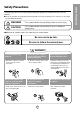
To prevent injury to the user or other people and property damage, the following instructions must be followed. ■ Incorrect operation due to ignoring of instruction will cause harm or damage. The seriousness is classified by the following indications. WARNING : This symbol indicates the possibility of death or serious injury. CAUTION symbol indicates the possibility of injury or damage to : This property only. ■ Meanings of symbols used in this manual are as shown below. Be sure not to do this.
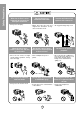
Safety Precautions When the air filter is to be removed, do not touch the metal parts of the unit. • It may cause an injury. When the unit is to be cleaned, switch off, and turn off the breaker. • Since the fan rotates at high speed during operation, it may cause an injury. Do not operate switches with wet hands. • It may cause an electric shock. Do not clean the air conditioner with water. • Water may enter the unit and degrade the insulation. It may cause an electric shock.
About the Controls on the Air Conditioner The controls will look like one of the following. Controls Model : HQ2081TH This automatically controls the temperature of the indoor air. Turn the knob so that arrow points to the higher number for greater cooling. Point the arrow to the lower number for more moderate cooling. (i.e. the higher the number, the greater the cooling) • FOR NORMAL COOLING 1. Turn the operation switch to the High Cool or the Low Cool setting. 2.
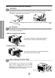
Additional controls and important information. Ventilation The ventilation lever must be in the CLOSE position in order to maintain the best cooling conditions. When fresh air is necessary in the room, set the ventilation lever to the OPEN position. The damper is opened and room air is drawn out. Part B Part A About the Controls on the Air Conditioner CLOSE VENT OPEN NOTE: Before using the ventilation feature, and prior to installing the front grille, pull down part level with part .
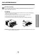
Care and Maintenance TURN THE AIR CONDITIONER OFF AND REMOVE THE PLUG FROM THE POWER OUTLET. Air Filter Cleaning The air filter behind the front grille should be checked and cleaned at least once every 2 weeks or more often if necessary. TO REMOVE: CAUTION: DO NOT operate the air conditioner without a filter because dirt and lint will clog it and reduce performance. 7 About the Controls on the Air Conditioner 1.
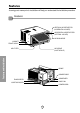
Features Learning parts name prior to installation will help you understand the installation procedure.
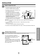
INSTALLATION How to Install the Unit 1. To prevent vibration and noise, make sure the unit is installed securely and firmly 2. Install the unit where the sunlight does not shine directly on the unit. 3. The outside of the cabinet must extend outward for at least 28cm (11") and there should be no obstacles, such as a fence or wall, within 50.8cm (20") from the back of the cabinet because it will prevent heat radiation of the condenser.
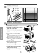
Installation Kit Contents 2 1 5 6 3 4 7 8 13 12 10 9 11 14 NO. 1 2 3 4 5 6 7 8 9 10 11 12 13 14 NAME OF PARTS Q'TY FRAME CURTAIN 2 SILL SUPPORT 2 BOLT 2 NUT 2 16 SCREW(TYPE A) (10mm(2/5")) D5.1mm(0.2") SCREW(TYPE B) 16mm(0.63") 3 D4.1mm(0.17") SCREW(TYPE C) 16mm(0.
Cabinet Installation 1. Open the window. Mark a line on center of the window sill (or desired air conditioner location). Carefully place the cabinet on the window sill and align the center mark on the bottom front with the center line marked in the window sill. Upper Guide Window sill Front Angle Fig. Window Sash 2. Pull the bottom window sash down behind the upper guide until it meets. Upper guide 1 9 Foam-pe 13 Cabinet Frame Curtain 1 Foam-pe 10 3.
9. Attach each Frame curtain to the window sash using screws (Type C). (See Fig. 6) Type C CAUTION: DO NOT DRILL A HOLE IN THE BOTTOM PAN. The unit is designed to operate with approximately 12.7mm (1/2") of water in bottom pan. 7 Fig. 6 10. Slide the unit into the cabinet. (See Fig. 7) CAUTION: For security purposes, reinstall screws (Type A) at cabinet's sides. Power cord Screw (Type A) Screw (Type A) Foam-Strip 11.
Electrical Data Line Cord Plug Use Wall Receptacle Do not under any circumstances cut or remove the grounding prong from the plug. Power supply cord with 3-prong grounding plug Power Supply Use 15 AMP, time delay fuse or circuit breaker. Standard 125V, 3-wire grounding receptacle rated 15A, 125V AC USE OF EXTENSION CORDS Because of potential safety hazards, we strongly discourage the use of an extension cord.
Electrical Safety IMPORTANT (PLEASE READ CAREFULLY) Because of potential safety hazards, we strongly discourage the use of an adapter plug. However, if you wish to use an adapter, a TEMPORARY CONNECTION may be made. Use UL-listed adapter, available from most local hardware stores (Fig. 17). The large slot in the adapter must be aligned with the large slot in the receptacle to assure a proper polarity connection.
Before you call for service... Troubleshooting Tips save time and money! Review the chart below first and you may not need to call for service. Normal Operation • You may hear a pinging noise caused by water being picked up and thrown against the condenser on rainy days or when the humidity is high. This design feature helps remove moisture and improve efficiency. • You may hear the thermostat click when the compressor cycles on and off.
Precauciones Importantes de seguridad Precauciones Importantes de Seguridad Instrucciones de Funcionamiento Instrucciones de Funcionamiento Precauciones Importantes de seguridad ....................17 Características e Instalacion Escriba aquí los números de serie y modelo de las unidades exterior e interior: Nº de Modelo Nº Serie Los números figuran en una etiqueta en el lateral de cada unidad. Distribuidor Fecha de compra Controles ...........................19 Ventilación.........................
Para prevenir tanto lesiones al usuario u otras personas como daños materiales, es preciso seguir estas instrucciones. ■ El manejo incorrecto debido a la inobservancia de estas instrucciones puede causar lesiones o daños cuya gravedad está clasificada en las siguientes indicaciones. ADVERTENCIA Este símbolo indica la posibilidad de lesiones mortales o graves. PRECAUCION Este símbolo indica la posibilidad de lesiones o daños materiales.
Precauciones Importantes de seguridad PRECAUCION Cuando se vaya a quitar el filtro de aire no toque las partes metálicas de la unidad interior. No limpie el acondicionador de aire con agua. Ventile bien cuando utilice el acondicionador junto con una estufa, etc. • El agua podría entrar en la unidad y degradar el aislamiento. También podría causar una sacudida eléctrica. • En este caso tal vez se produzca una falta de oxígeno.
Instruccionnes de Funcionamiento La apariencia de los controles será como uno de los siguientes. Controles Modelo : HQ2081TH :Apaga el aire acondicionado. :Permite la operación de la velocidad media del ventilador sin enfriar. Low Fan(Ventilador Bajo) :Permite la operación de la velocidad baja del ventilador sin enfriar. High Cool(Enfriamiento Alto) :Permite enfriar con la operación de la velocidad alta del ventilador.
Controles adicionales e informacion importante. Ventilación La palanca de ventilación debe estar en posición CERRADA para poder mantener las mejores condiciones de enfriamiento. Cuando se necesite aire fresco en la habitación, coloque la palanca de ventilación en posición ABIERTA. La Compuerta es abierta y el aire de la habitación es expulsado. Parte B Parte A Instrucciones de Funcionamiento CERRADO VENT ABIERTO NOTA: Antes de utilizar la característica de ventilación, haga un kit de ventilación.
Cuidado y Mantenimiento APAGUE EL AIRE ACONDICIONADO Y SAQUE EL ENCHUFE DEL TOMA CORRIENTE DE LA PARED. Limpieza de filtro de Aire El filtro de aire detrás de la rejilla frontal debe ser revisado y limpiado por lo menos una vez por cada dos semanas o más frecuentemente si es necesario. La rejilla es diseñado para limpiar el filtro tanto hacia arriba como hacia abajo.
Características Aprender el nombre de las partes antes de la instalación le ayudará a entender el proceso de instalación.
Instrucciones de Instalación Elija el major lugar ; ; Cerca Pabellón Aire frio Radiacion de calor 30"~60" 1. Para prevenir la vibración y el ruido, asegure de que la unidad esté instaalada segura y firmemente. 2. Instale la unidad donde el sol no refleje directamente en la unidad. 3. La salida debe extenderse hacia afuera por lo menos 11" y no debe haber obstáculos, como cercas o paredes, en 20" de la parte de atrás del gabinete porque va ha prevenir la rediación de calor del condensador.
Contenido del Juego de Instalación 2 1 5 6 3 4 7 8 12 NO. 1 2 3 4 5 6 7 8 9 10 11 12 13 14 13 10 9 11 14 NOMBRE LA PARTE CANTIDAD PANEL GUÍA 2 SOPORTE DE ALFÉIZAR 2 TORNILLO 2 TUERCA 2 TORNILLO(TIPO A) 16 TORNILLO(TIPO B) D5.1mm(0.2") 3 16mm(0.63") TORNILLO(TIPO C) D4.1mm(0.17") 5 16mm(0.
Instalación del Gabinete 1. Abra la ventana. Marque una línea en el centro del banqueta de la ventana(o la ubicación deseada del aire acondicionado). Cuidadosamente ubique el gabinete en la banqueta de la ventana y alinee la marca central en el frente inferior con el centro de la línea marcada en la banqueta de la ventana. 2. Hale hacia abajo la parte inferior de la ventana hasta que se una detrás de la guía superior. Guía Superior Taburete de la Ventana Angulo de Delante Fig.
9. Adjunte cada panel guía a cada lado de la (Tipo C). ventana usando tornillos (Ver Fig. 6) Tipo C PRECAUCION: No perfore la charola del fondo. La unidad está diseñada para operar con aproximadamente 1/2" de agua en la charola del fondo. 7 Fig. 6 10. Deslice el chasís dentro del gabinete. (Ver Fig. 7) Conrdon de Alimentacion CUIDADO: Por razones de seguridad, re instale los tornillos(Tipo A) en los lados del gabinete. Tornillo(Tipo A) Tornillo(Tipo A) 11.
Datos Electricos Corc n El ctrico Utilice el enchufe de la pared No lo corte bajo ninguna circunstancia o remueva la punta del enchufe. Cord n el ctrico con puntas para enchufar Standard 125V, enchufe de 3 L neas de 15A, 125V AC Consumo de Energ a Utilice un fusible de 15AMP o un Interruptor USO DE CORDONES DE EXTENSION Debido al potencial de peligro a su seguridad bajo ciertas circunstancias recomendamos encaredidamente no utiliar cordones de extensión.
Informacion Electrica Debido al peligro potencial, nosotros no recomendamos el uso de adaptadores. Sin embargo, si usted desea utilizar un adaptador, una CONEXIÓN TEMPORAL, puede ser efectuada. Utilice adaptadores UL, disponibles en la mayoría de los estable cimientos de herramientas(Fig. 17). La pata mas grande del adaptador debe ser alineada con la pata mas grande del interruptor para asegurarse una polarización adecuada.
Antes de avisar al Servicio Técnico Tips para solucionar problemas (Ahorre temopo y dinero) Cuando tenga algún problema primero consulte el cuadro que se encuentra abajo y tal vez no necesite llamar para solicitar servicio técnico. Operación normal • Durar te dias lluviosos o cuando la humedad es alta usted puede escuchar un ruido metállco causa do por agua recogida y arrojada contra el condensador. Esta caracteristica ayuda a remover la humedad y mejorar la eficiencia.
PRODUCT SPECIFICATION ESPECIFICIONES DEL PRODUCTO Model Modèle Modelo HQ-2081TH COOLING CAPACITY CAPACITÉ DE REFROIDISSEMENT CAPACIDAD DE ENFRIAMIENTO ELECTRICAL RATING CARACTÉRISTIQUES ÉLECTRIQUES CLASIFICION DE LA ELECTRICIDAD Btu/h Phase Phase Fase 8,000 Single Simple Monofasico Frequency Fréquence Frecuencia (Hz) 60 Voltage Tension Voltaja (V) 115 Current Courant Corriente (Amps) (A) (Amps) 7.6 Input Consommation Potencia (W) 820 EER RENDEMENT ÉNERGÉTIQUE EER 9.
Nota 31
Panasonic Consumer Electronics Company, Division of Matsushita Electric Corporation of America One Panasonic Way Secaucus, New Jersey 07094 Panasonic Sales Company, Division of Matsushita Electric of Puerto Rico, Inc., Ave. 65 de Infanteria, Km. 9.