Room Air Conditioner INSTALLATION AND OPERATING INSTRUCTIONS Model: HQ-2244UH Please read these operating instructions thoroughly before using your air conditioner and keep for future reference. For assistance, please call: 1-800-211-PANA(7262) or Register your product at : http://www.panasonic.
Safety Precautions Safety Precautions Safety Precautions .............3 FOR YOUR RECORDS Staple your receipt to this page in case you need it later. Write down the model and serial numbers here: Model # Serial # You can find them on a label on the side of each unit. Dealer's Name Before you call for service... Features and Installation About the Controls on the Air Conditioner Date Purchased About the Controls on the Air Conditioner Controls..............................5 Ventilation ................
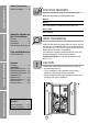
To prevent injury to the user or other people and property damage, the following instructions must be followed. ■ Incorrect operation due to ignoring of instruction will cause harm or damage. The seriousness is classified by the following indications. WARNING : This symbol indicates the possibility of death or serious injury. CAUTION symbol indicates the possibility of injury or damage to : This property only. ■ Meanings of symbols used in this manual are as shown below. Be sure not to do this.
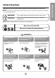
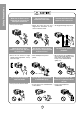
Safety Precautions When the air filter is to be removed, do not touch the metal parts of the unit. • It may cause an injury. When the unit is to be cleaned, switch off, and turn off the breaker. • Since the fan rotates at high speed during operation, it may cause an injury. Do not operate switches with wet hands. • It may cause an electric shock. Do not clean the air conditioner with water. • Water may enter the unit and degrade the insulation. It may cause an electric shock.
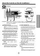
About the Controls on the Air Conditioner Controls 2 6 OPERATION 1 TEMP 8 TIMER 6 3 7 MODE 2 FAN SPEED 4 ECONOMY 5 4 3 7 Precaution: The Remote Controller will not function properly if strong light strikes the sensor window of the air conditioner or if there are obstacles between the Remote Control unit and the air conditioner. OPERATION BUTTON • To turn the air conditioner ON, push the button. To turn the air conditioner OFF, push the button again.
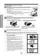
Additional controls and important information. Ventilation The ventilation lever must be in the CLOSE position in order to maintain the best cooling conditions. When fresh air is necessary in the room, set the ventilation lever to the OPEN position. The damper is opened and room air is drawn out. CLOSE VENT OPEN Part B About the Controls on the Air Conditioner NOTE: Before using the ventilation feature, and prior to installing the front grille, pull down part until level with part .
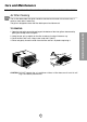
Care and Maintenance TURN THE AIR CONDITIONER OFF AND REMOVE THE PLUG FROM THE POWER OUTLET. Air Filter Cleaning The air filter behind the front grille should be checked and cleaned at least once every 2 weeks or more often if necessary. The grille is designed to clean the filter both upward and downward. TO REMOVE: CAUTION: DO NOT operate the air conditioner without a filter because dirt and lint will clog it and reduce performance. 7 About the Controls on the Air Conditioner 1.
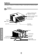
Features Learning parts name prior to installation will help you understand the installation procedure.
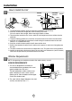
Installation How to Install the Unit INSIDE OUTSIDE FOAM HEAT RADIATION 1/4 Bubble 30-60" COOLED AIR Level FENCE AWNING About 1/2" Over 20" Window Requirements NOTE: All supporting parts should be secured to firm wood, masonry, or metal. WINDOW REQUIREMENTS 1. This unit is designed for installation in standard double hung windows with actual opening widths from 26" to 41".
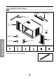
Installation Kits Contents Foam strip (Plain-Back) Foam-PE (Adhesive-Backed) Foam-PE (Adhesive-Backed) Left frame curtain Drain pipe Window locking bracket Features and Installation Right frame curtain Sill bracket(2) Type A (14) Support bracket(2) Type B (7) Type C (5) Type D (2) ■ Top retainer bar is in product package.
Suggested Tool Requirements SCREWDRIVER(+, -), RULER, KNIFE, HAMMER, PENCIL, LEVEL PREPARATION OF CHASSIS Shipping screws 1. Remove the screws which fasten the cabinet at both sides and at the back.(See Fig. 1) 2. Slide the unit out from the cabinet by gripping the base pan handle and pulling forward while bracing the cabinet.(See Fig. 2) 3. Cut the window sash seal to the proper length. Peel off the backing and attach the Foam-PE to the underside of the window sash.(See Fig. 3) Fig. 1 4.
Cabinet Installation 1. Open the window. Mark a line on the center of the window stool between the side window stop moldings. Loosely attach the sill bracket to the support bracket using the carriage bolt and the lock nut. (See Fig. 5) 2. Attach the sill bracket to the window sill using the screws (Type B). Carefully place the cabinet on the window stool and align the center mark on the bottom front with the center line marked window stool.(See Fig.
5. Pull each Frame curtain fully to each window sash track, and pull the bottom window sash down behind the Top retainer bar until it meets. Screw(Type C) 6. Attach each Frame curtain the window sash by using screws (Type C.) (See Fig. 9) Fig. 9 7. Slide the unit into the cabinet.(See Fig. 10) CAUTION: For security purpose, reinstall screws at cabinet's sides. Power Cord Screw Screw Fig. 10 8. Cut the Foam-strip to the proper length and insert between the upper window sash and the lower window sash.
Electrical Data(For 230/208V model only) Line Cord Plug Use Wall Receptacle Do not under any circumstances cut or remove the grounding prong from the plug. Power supply cord with 3-prong grounding plug Use 15 AMP. time delay fuse or 15 AMP. circuit breaker. Standard 250V, 3-wire grounding receptacle rated 15A, 250V AC Do not under any circumstances cut or remove the grounding prong from the plug. Power supply cord with 3-prong grounding plug Power Supply Use 20 AMP. time delay fuse or 20 AMP.
Before you call for service... Troubleshooting Tips Save time and money! Review the chart below first and you may not need to call for service. Normal Operation • You may hear a pinging noise caused by water being picked up and thrown against the condenser on rainy days or when the humidity is high. This design feature helps remove moisture and improve efficiency. • You may hear the relay click when the compressor cycles on and off.
Precauciones Importantes de seguridad PARA SU INFORMACION Precauciones Importantes de seguridad ....................17 Escriba aquí los números de serie y modelo de las unidades exterior e interior: Instrucciones de Funcionamiento Instrucciones de Funcionamiento Antes de avisar al Servicio Técnico Características e Instalacion Precauciones Importantes de Seguridad Nº de Modelo Nº Serie Los números figuran en una etiqueta en el lateral de cada unidad. Distribuidor Fecha de compra Controles .......
Para prevenir tanto lesiones al usuario u otras personas como daños materiales, es preciso seguir estas instrucciones. ■ El manejo incorrecto debido a la inobservancia de estas instrucciones puede causar lesiones o daños cuya gravedad está clasificada en las siguientes indicaciones. ADVERTENCIA Este símbolo indica la posibilidad de lesiones mortales o graves. PRECAUCION Este símbolo indica la posibilidad de lesiones o daños materiales.
Precauciones Importantes de seguridad PRECAUCION Cuando se vaya a quitar el filtro de aire no toque las partes metálicas de la unidad interior. No limpie el acondicionador de aire con agua. Ventile bien cuando utilice el acondicionador junto con una estufa, etc. • El agua podría entrar en la unidad y degradar el aislamiento. También podría causar una sacudida eléctrica. • En este caso tal vez se produzca una falta de oxígeno.
Instruccionnes de Funcionamiento Controles 2 6 OPERATION 1 TEMP 8 TIMER 6 3 7 MODE 2 FAN SPEED 4 ECONOMY 5 4 3 7 Precaución: El dispositivo de control remoto no funcionará adecuadamente si la ventana sensora del acondicionador de aire es expuesta a luz fuerte, o si hay obstáculos entre el dispositivo de control remoto y el acondicionador de aire.
Controles adicionales e informacion importante. Ventilación La palanca de ventilación debe estar en posición CERRADA para poder mantener las mejores condiciones de enfriamiento. Cuando se necesite aire fresco en la habitación, coloque la palanca de ventilación en posición ABIERTA. La Compuerta es abierta y el aire de la habitación es expulsado. CERRADO Instrucciones de Funcionamiento NOTA: Antes de utilizar la característica de ventilación, haga un kit de ventilación.
Cuidado y Mantenimiento Apague el aire acondicionado y saque el enchufe del toma corriente de la pared. Limpieza de filtro de Aire El filtro de aire detrás de la rejilla frontal debe ser revisado y limpiado por lo menos una vez por cada dos semanas o más frecuentemente si es necesario. La rejilla es diseñado para limpiar el filtro tanto hacia arriba como hacia abajo.
Características Aprender el nombre de las partes antes de la instalación le ayudará a entender el proceso de instalación.
Instrucciones de Instalación Elija el major lugar TOLDO BARDA FOAM 1/4 Ampolla RADIACION DE CALOR 30-60" AIR ENFRIADO Nivel APROXIMADAMENTE 1/ 2 ARRIBA DE 20" 1. Para evitar vibración y ruido, asefúrese de que la unidad esté instalada de manera segura y firmemente. 2. Instale la unidad en lugares fuera de luzsolar directa directamente sobre la unidad. 3.
Contenido del juego de instalación TIRA DE GOMA CINTA DE ESPUMA CINTA DE ESPUMA PANEL GUÍA Tapa del desagüe SOPORTE DE CERRADURA Características e Instalacion PANEL GUÍA MENSULA DE SOPORTE (2) MENSULA DEL ALFEIZAR (2) TIPO A (14) TIPO B (7) TIPO (5) TIPO D (2) ■ La barra de retención superior está en el empaque del producto.
Requisitos de las herramientas sugeridas DESARMADOR ( , ), REGLA, CUCHILLO, MARTILO, LAPIZ, NIVEL PREPARACION DEL CHASIS 1. Retire los 4 tornillos que unen el gabinete a la parte posterior y lateral de la unidad. (Ver Fig.1) 2. Deslice la unidad fuera del gabiete tomando la manija de la charola de la base y jale hacia adelante miéntras sostiene el gabinete. (Ver Fig.2) 3. Corte el sellode chasis de la ventana a la longitud apropiada.
Instalacion del Gabinete 1. Abra la ventana. Marque una línea en el centro de la repisa de la ventana entre las molduras de tope de la ventana lateral. Coloque sin apretar la ménsula del alféizar en la ménsula de soporte utilizando el pemo y la tuerca de segutidad.(Ver Fig.5) 2. Coloque la ménsula del alféizar en el alféizar de la ventana utilizando los tornillos (Tipo B). Apriete el perno y la tuerca de seguridad.
5. Hale cada panel guía completamente a cada lado de la ventana y repita del paso 2. TORNILLO (TIPO C) 6. Adjunte cada panel guía a cada lado de la ventana usando tornillos (Tipo C). (Ver Fig. 9) Fig. 9 7. Deslice el chasís dentro del gabinete. (Ver Fig.10) CUIDADO: Por razones de seguridad, re instale los tornillos en los lados del gabinete. CORDÓN DE ALIMENTACIÓN ELÉTRICA TORNILLO TORNILLO Fig. 10 8.
Datos Electricos (Para modelo de 230/208V Solamente) Corcón Eléctrico Utilice el enchufe de la pared No lo corte bajo ninguna circunstancia o remueva la punta del enchufe. Cordón eléctrico con puntas para enchufar Utilice un fusible de 15AMP. o un Interruptor de 15AMP. Standard 250V, enchufe de 3 Líneas de 15A, 250V AC No lo corte bajo ninguna circunstancia o remueva la punta del enchufe. Cordón eléctrico con puntas para enchufar Consumo de Energía Utilice un fusible de 20AMP.
Antes de avisar al Servicio Técnico Tips para solucionar problemas (Ahorre temopo y dinero) Cuando tenga algún problema primero consulte el cuadro que se encuentra abajo y tal vez no necesite llamar para solicitar servicio técnico. Operación normal • Durar te dias lluviosos o cuando la humedad es alta usted puede escuchar un ruido metállco causa do por agua recogida y arrojada contra el condensador. Esta caracteristica ayuda a remover la humedad y mejorar la eficiencia.
PRODUCT SPECIFICATION ESPECIFICIONES DEL PRODUCTO Model Modèle Modelo HQ-2244UH COOLING CAPACITY CAPACITÉ DE REFROIDISSEMENT CAPACIDAD DE ENFRIAMIENTO ELECTRICAL RATING CARACTÉRISTIQUES ÉLECTRIQUES CLASIFICION DE LA ELECTRICIDAD Btu/h Phase Phase Fase 23,500/23,000 Single Simple Monofasico Frequency Fréquence Frecuencia (Hz) 60 Voltage Tension Voltaja (V) 230/208 Current Courant Corriente (Amps) (A) (Amps) 11.2/12.
Nota 31
Panasonic Consumer Electronics Company, Division of Matsushita Electric Corporation of America One Panasonic Way Secaucus, New Jersey 07094 Panasonic Sales Company, Division of Matsushita Electric of Puerto Rico, Inc., Ave. 65 de Infanteria, Km. 9.