AirborneTM Wireless 802.
Copyright © 2006-2007 QUATECH, Inc. ALL RIGHTS RESERVED. No part of this publication may be copied in any form, by photocopy, microfilm, retrieval system, or by any other means now known or hereafter invented without the prior written permission of QUATECH, Inc. This document may not be used as the basis for manufacture or sale of any items without the prior written consent of QUATECH, Inc. QUATECH is a registered trademark of QUATECH, Inc. Airborne™ is a trademark of QUATECH, Inc.
CONTENTS CHAPTER 1 INTRODUCTION .................................................................................................................... 1 1.1 OVERVIEW ...................................................................................................................................... 1 1.2 CONFIGURATIONS ............................................................................................................................ 1 1.3 FEATURES.....................................................
Contents 3.3 3.4 CIRCUIT BOARD LAYOUT PRACTICES .............................................................................................. 27 EMI / RFI GUIDELINES............................................................................................................... 28 CHAPTER 4 WIRELESS SECURITY .................................................................................................. 29 4.1 WPA AND LEAP SECURITY.......................................................................
Contents LIST OF FIGURES Figure 1. Airborne WLN Module Hardware Block Diagram ..........................................................9 Figure 2. Antenna Connectors ....................................................................................................16 Figure 3. Power-up Sequence (Separate /RESET Signal) .........................................................17 Figure 4. Power-up Sequence (/RESET Tied to DVDD)...............................................................17 Figure 5.
Contents LIST OF TABLES Table 1. Airborne WLN Module Configurations ............................................................................1 Table 2. Airborne WLN Module Specifications .............................................................................8 Table 3. Airborne WLN Module Pin Assignments.......................................................................12 Table 4. F0, F2, F3, F6 and RF_LED Signal Assignments.........................................................14 Table 5.
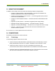
CHAPTER 1 INTRODUCTION 1.1 OVERVIEW The Airborne™ family is a line of highly integrated 802.11 wireless products based on the Airborne Wireless LAN Node Module. The Airborne Wireless LAN Node Module includes a radio, a baseband processor, an application processor, and firmware for a "drop-in" Wi-Fi solution.
1 - Introduction 1.3 FEATURES The following list describes the key features of the Airborne WLN Module. 802.
1 - Introduction 1.5 USING THIS DOCUMENT In addition to this chapter, this book contains the following chapters and appendixes: Chapter 2, Airborne Wireless LAN Node Module ⎯ describes the hardware and software characteristics of the Airborne WLN Module. Chapter 3, Recommended Layout Practices ⎯ provides suggested layout practices for the Airborne WLN Module. Chapter 4, Serial Peripheral Interface ⎯ describes the Airborne WLN Module’s SPI interface.
1 - Introduction 1.6.2 Notes A note is information that requires special attention. The following convention is used for notes. Note: 1.6.3 A note contains information that deserves special attention. Cautions A caution contains information that, if not followed, can cause adverse consequences or damage to the product. The following convention is used for cautions. A caution contains information that, if not followed, can cause damage to Caution: the product or adverse consequences to the user. 1.
1 - Introduction 1.7 RELATED DOCUMENTATION In addition to this document, other related documents are on the supplied CD. These documents are provided as Portable Document Format (PDF) files. To read them, you need Adobe® Acrobat® Reader® 4.0.5 or higher. For your convenience, Adobe Reader is on the CD. For the latest version of Adobe Acrobat Reader, go to the Adobe Web site: www.adobe.com.
1 - Introduction This page intentionally left blank Page 6 Airborne Wireless LAN Node Module Data Book Quatech, Inc.
CHAPTER 2 AIRBORNE WIRELESS LAN NODE MODULE 2.1 OVERVIEW This chapter describes the hardware and software characteristics of the Airborne WLN Module. Topics in this chapter include: 2.2 Specifications (page 8) 2.3 Block Diagram (page 9) 2.4 Hardware Description (page 9) 2.5 Host Pin Assignments and Signal Descriptions (page 12) 2.6 Antenna Pin Assignments and Descriptions (page 16) 2.7 Reset (page 16) 2.8 Airborne WLN Module Operation (page 19) 2.
2 – Airborne Wireless LAN Node Module 2.2 SPECIFICATIONS Table 2. Airborne WLN Module Specifications Specification Description Technology IEEE 802.11b/g, WiFi compliant (802.11i, 802.11e, 802.11d capable) Frequency 2.400 – 2.4835 GHz (US/Can/Japan/Europe) 2.471 – 2.497 GHz (Japan) Modulation Technology DSSS, CCK, OFDM Modulation Type DBPSK, DQPSK, CCK, BPSK, QPSK, 16QAM, 64QAM Clock Frequencies 4.8 MHz – CPU reference clock 32.
2 – Airborne Wireless LAN Node Module 2.3 BLOCK DIAGRAM Figure 1 shows the block diagram of the Module hardware. Figure 1. Airborne WLN Module Hardware Block Diagram 2.4 HARDWARE DESCRIPTION The Module contains all of the hardware and firmware components required to implement a full Wireless Fidelity (Wi-Fi)-compatible IEEE 802.11b/g network interface. It includes two antenna connections, along with all required RF, baseband, and application-processor circuitry.
2 – Airborne Wireless LAN Node Module 2.4.1 Application Processor The application processor interfaces to the radio module and is the link between the wireless LAN and the embedded Host application. A TCP/IP stack with TCP server and client capabilities, an RTOS kernel, a radio Link Layer interface, and a Host application layer Command Line Interface all support features required for flexible LAN connectivity.
2 – Airborne Wireless LAN Node Module 2.4.7 Transmit/Receive Switch The Transmit/Receive (T/R) Switch selects the appropriate signal path for the antenna during transmit and receive operations. The IEEE 802.11 MAC controls the T/R Switch automatically. 2.4.8 A/B Diversity Switch The A/B Diversity Switch controls whether Antenna 1 (J1) or Antenna 2 (J2) is selected. The IEEE 802.11 MAC controls the A/B Diversity Switch automatically when diversity is enabled.
2 – Airborne Wireless LAN Node Module 2.5 HOST PIN ASSIGNMENTS AND SIGNAL DESCRIPTIONS The interconnect between the Module and the Host system is a 4 mm high, 36-pin, Hirose DF12-36DS-0.5 V(80) connector. The part number for the 4-mm high mating connector to be mounted on the PCB is the Hirose DF12-36DP-0.5 V(80). Table 3 lists the Module’s Host pin assignments. Table 3. Airborne WLN Module Pin Assignments Pin Signal 1 GND Ground 2 TSI ISP Serial Data In (see Note 1) 3 DVDD Power, +3.
2 – Airborne Wireless LAN Node Module Table 3. Airborne WLN Module Pin Assignments Pin Signal Sink Source Description 21 G7 4 mA 4 mA Used as analog input or digital output (see Table 6). Provides 3.3 V CMOS-compatible digital output (VOL≤0.4, 2.4 V≤ VOH). 22 G0 4 mA 4 mA UART: Used as analog input or digital output (see Table 6). Provides 3.3 V CMOS-compatible digital output (VOL≤0.4, 2.4 V≤ VOH). SPI: Used as system interrupt (see Table 5). Signal is 3.3 V TTL-compatible and 5 V tolerant.
2 – Airborne Wireless LAN Node Module Table 4. F0, F2, F3, F6 and RF_LED Signal Assignments Direction Port Status* F0 Status Description POST Indicates that the Module has passed its Power On Self Test (POST). F2 RF LINK F3 WLAN CFG LINK Indicates that the Module has a Dynamic Host Configuration Protocol (DHCP) or static IP configuration. Indicates that the Module has associated with an Access Point or peer.
2 – Airborne Wireless LAN Node Module Table 7. E4, E5, E6, E7 Signal Assignments Port 100-8004-102G Digital E4 Digital In/Out E5 Digital In/Out E6 Digital In/Out E7 Digital In/Out Airborne Wireless LAN Node Module Data Book Quatech, Inc.
2 – Airborne Wireless LAN Node Module 2.6 ANTENNA PIN ASSIGNMENTS AND DESCRIPTIONS Figure 2 shows the Module antenna connectors and Table 8 describes their pin assignments. J2 is used for single-antenna operation. To implement antenna diversity, use both J1 and J2. J2 Table 8. Airborne WLN Module Antenna Pin Assignments Pin Description J1 (left connector) Antenna 1 - Secondary J2 (right connector) Antenna 2 - Primary Figure 2. Antenna Connectors 2.
2 – Airborne Wireless LAN Node Module DVdd /RESET POR Startup Timer (Timeout) WUDX Internal Reset Signal Figure 3. Power-up Sequence (Separate /RESET Signal) Figure 4 shows the on-chip POR sequence in which the /RESET and DVDD pins are tied together. The DVDD signal is stable before the startup timer expires. In this case, the CPU receives a reliable reset. DVdd /RESET POR 70ns Startup Timer (Timeout) Internal Reset Signal Figure 4.
2 – Airborne Wireless LAN Node Module DVdd Airborne WLN Module /RESET Figure 6. External Reset Circuit In Figure 6: The diode D discharges the capacitor when DVDD is powered down. R1 = 100 Ω to 1K Ω limits any current flowing into /RESET from external capacitor C1. This protects the /RESET pin from breakdown due to Electrostatic Discharge (ESD) or Electrical Overstress (EOS). R2 < 40K Ω is recommended to ensure that voltage drop across R2 leaves the /RESET pin above a VIHGP level.
2 – Airborne Wireless LAN Node Module 2.8 AIRBORNE WLN MODULE OPERATION 2.8.1 Power-up When the Module powers-up, it performs a Power On Self Test (POST). The POST procedure checks that RAM, Flash memory, real-time clock, and radio are operating as expected. If the Module passes the POST, the POST line is set high (POST). Any failures cause the Module to reset. 2.8.2 Factory Reset The Module provides a factory-reset function that returns the Module to its original factory default settings.
2 – Airborne Wireless LAN Node Module 2.9 DESIGN GUIDELINES 2.9.1 General Design Guidelines The Module is designed to be implemented into a variety of applications. Any design must meet the following guidelines: Provide 3.3 V to all DVdd power pins. Provide ground connections to all Vss pins. Tie port G3 to the Module’s 2.5 V Vref through a 10 KΩ resistor to prevent the Module from resetting itself to factory defaults at startup. Tie all unused I/O to ground via 10 KΩ resistors.
2 – Airborne Wireless LAN Node Module The Configuration Status must be available to be shifted out of the MISO port at the beginning of each command, requiring its update immediately at the end of a frame to be prepared for the next frame. A pre-defined data frame has to be agreed upon by both the master and slave for the exchange of data. The data frame is described by two parameters, the clock polarity and the clock phase. These parameters have four possible states that correspond to four SPI Modes.
2 – Airborne Wireless LAN Node Module Connect the application’s MISO line to port F1 of the WLN to receive data from the Slave. Connect the application’s SCK line to port F4 of the WLN to send the Master’s serial clock. Connect the application’s /SS line to port F5 of the WLN to select the WLN Module. Connection the application’s INT line to port G0 of the WLN to receive interrupts from the Slave. This indicates that data is available on the WLN.
2 – Airborne Wireless LAN Node Module 2.10 PACKAGE CONFIGURATION Figure 7. Mechanical Dimensions (Airborne WLN Module) 100-8004-102G Airborne Wireless LAN Node Module Data Book Quatech, Inc.
2 – Airborne Wireless LAN Node Module 2.11 2.11.1 ELECTRICAL CHARACTERISTICS Absolute Maximum Ratings Table 10 shows the absolute maximum ratings for supply voltage and voltages on the Module’s digital and analog pins. Exceeding these values will permanently damage the Module. Table 10. Absolute Maximum Ratings Max Unit Peak instantaneous operating current Parameter Min 625 mA Startup inrush current 3000 mA Voltage at GPIO pins -0.3 5.7 V Voltage at Analog pins -0.3 2.
2 – Airborne Wireless LAN Node Module 2.11.2 Electrical Characteristics Table 11. Electrical Characteristics Symbol VDD IDDTX IDDRX Parameter Min Typ Max Unit 3.135 3.3 3.465 V Transmit Mode Current 11b mode at +15 dBm RF power 575 625 mA Transmit Mode Current 11g mode at +12 dBm RF power 485 535 mA Receive Mode Current 375 400 mA Supply Voltage (3.3 V ±5%) VIHGP GPIO Input High voltage VILGP GPIO Input Low voltage 1.8 V 1.
2 – Airborne Wireless LAN Node Module 2.11.3 AC Electrical Characteristics – Receiver Table 12. RF Performance Receive Sensitivity 2.11.4 Data Rate Sensitivity 54.0 Mb/s 36.0 Mb/s -71 dBm -77 dBm 18.0 Mb/s -83 dBm 11.0 Mb/s -85 dBm 1.0 Mb/s -87 dBm AC Electrical Characteristics – Transmitter Transmit power is managed by the Module automatically. The maximum transmit output power is typically +15 dBm for 802.11b mode and +12 dBm for 802.11g mode. These are RMS power values. 2.11.
CHAPTER 3 RECOMMENDED LAYOUT PRACTICES 3.1 OVERVIEW This chapter contains recommended layout practices. Topics covered in this chapter include: 3.2 Module Mounting Guidelines (below) 3.3 Circuit Board Layout Practices (below) 3.4 EMI/RFI Guidelines (page 28) 3.2 MODULE MOUNTING GUIDELINES Special care must be observed when placing the Airborne WLN Module. In particular: The antenna must not be mounted below any other printed circuit boards, components, or metallic housing. 3.
3 – Recommended Layout Practices 1.17 [29.7] 0.83 [21.1] 3XØ0.09 [Ø2.2] 0.17 [4.3] 1.60 [40.6] 1.26 [32.0] 0.004[0.1] 36 2 35 1 THIS AREA CLEAR FROM INTERCONNECT AND COMPONENTS 0.41[10.5] 0.17 [4.3] inch [mm] Figure 8. Guidelines for Mounting the Airborne WLN Module 3.4 EMI / RFI GUIDELINES To minimize electromagnetic interference (EMI) and radio-frequency interference (RFI), pay strict attention to power and signal routing near the Module.
CHAPTER 4 WIRELESS SECURITY 4.1 WPA AND LEAP SECURITY The WPA and LEAP software modules provide advanced security configuration and communication services required by today’s enterprise-class deployments. Please refer to IEEE standard 802.1X 2001 (section 4) and IEEE standard 802.11i 2004 (section 4) for additional information. 4.1.
4 – Wireless Security Authentication Protocol (EAP), and features dynamic distribution and management of session keys. A RADIUS server is required for this security standard. “IEEE 802.11i” refers to the IEEE security standard officially ratified in June 2004 as part of the 802.11 family. 802.11i was tested and certified for interoperability by the Wi-Fi Alliance. In addition to improved encryption, this standard contains the 802.1X standard, improving key management and user authentication.
4 – Wireless Security In this release, the blank character (space) may not be included in a WPA Note: passphrase or LEAP password. 4.1.
4 – Wireless Security 4.1.3 Computer Resource Requirements WPA-PSK In order to function properly, an Access Point that supports WPA-PSK must be available. The WPA-PSK passphrase installed on the Access Point must match the passphrase configured on the WLN. LEAP In order to function properly, a RADIUS server configured for LEAP containing usernames/passwords, and an Access Point that supports LEAP, must be available.
4 – Wireless Security Once the WLN is authenticated, additional impacts include: Roaming A WLN configured for WPA-PSK can only roam to APs that have WPA-PSK enabled in the same ESS. A WLN configured for LEAP can only roam to APs that support LEAP, roaming, and are connected to the same RADIUS server. Data Throughput and Latency Round trip latency may increase and overall throughput may decrease, due to the additional steps to encrypt or decrypt data.
4 – Wireless Security This page intentionally left blank Page 34 Airborne Wireless LAN Node Module Data Book Quatech, Inc.
CHAPTER 5 SERIAL PERIPHERAL INTERFACE 5.1 OVERVIEW This chapter defines the DPAC Technologies Airborne SPI Module interface. The Host SPI interface is based on the Motorola SPI industry standard, which does not provide anything beyond a physical protocol. 5.2 SPI STANDARD SUPPORT SUMMARY The SPI Module (WLN) supports Serial Peripheral Interface (SPI) data communications. SPI is an industry standard, synchronous, serial link.
5 – Serial Peripheral Interface 5.4 SPI LOGICAL INTERFACE 5.4.1 SPI Read Configuration The SPI Slave Status may be obtained by sending the Read Configuration command. Read Configuration Table 14. SPI Read Configuration Command Command Length Value (0x40) RCONF 1 Octet Bit 7 Bit 6 Bits 5:0 =0 =1 = 0 (reserved, must be set to 0) Response The returned status is strictly informative and the Host should not assume that the Slave takes any particular action as the result of a status value sent.
5 – Serial Peripheral Interface 5.4.2 SPI Write Configuration This is an obsolete command and is no longer available. 5.4.3 SPI Write Data The SPI Master may write data to the Slave with the Write Data command. Write Data Command Table 15. SPI Write Data Command Command Length Value (0x80) WDATA 1 Octet Bit 7 Bit 6 Bits 5:0 =1 =0 = 0 (reserved, must set to 0) Response Length (2 Octets) – This tells the Master the maximum number of octets that may be transmitted to the Slave.
5 – Serial Peripheral Interface 5.4.4 SPI Read Data The SPI Master may read data when available by sending the Read Data command. Read Data Command Table 16. SPI Read Data Command Command Length Value (0x00) RDATA 1 Octet Bit 7 Bit 6 Bits 5:0 =0 =0 = 0 (reserved, must set to 0) Response Length (2 Octets) – This tells the Master the number of octets that are waiting to be transmitted to the Master.
APPENDIX A POWER CONTROL A.1 OVERVIEW This appendix describes issues associated with external power switches and illustrates a circuit for interfacing and controlling power to the Module from a 5 V system. A.2 INTRODUCTION Several applications, such as long-life battery-powered systems, require Wireless LAN Node (WLN) functionality in a limited-power environment, where there are long intervals between network accesses.
A – Power Control Figure 15. Inrush Current Characteristics Since the Module’s peak operating current is approximately 450 mA, the power budget for the Module is approximately the same. This is satisfactory for an always-on system. For an operating system, however, rapidly switching on the Module and its corresponding inrush requirement can cause system problems. Figure 16 shows the inrush problem on a 5 V system with a current-limited supply.
A – Power Control A.4 APPLICATION CIRCUIT Figure 17 shows a recommended application circuit that can be used to obviate the harmful effects described in this appendix. Table 17 shows the parts associated with the recommended application circuit. +5V 2 Low ESR Tantalum VIN +3.3V R1 1 GND C1 22uF 6 8 SD 10K,5% ERR 5 C2 22uF Low ESR Tantalum GND MICREL MIC2505-1BM 3 FLG 4 2 CTL 1 GATE 3 IN1 IN2 U1 OUT1 OUT2 5 7 C3 0.1uF NATIONAL LP3871ES-3.3 4 VOUT VR1 C4 0.
A – Power Control A.4.1 High-Side Switch The Micrel high-side switch is a single-channel power switch with slow turn-on characteristics. The device’s slow turn-on acts as an inrush current limiter and prevents large current spikes from dropping the power supply rail. Adding C4 (0.1 μF ceramic capacitor) on the GATE input of U1 slows the device’s switching time.
A – Power Control A.4.4 Circuit Performance Figure 18 shows the characteristics of the implemented circuit. The lower trace is the system’s +5 V supply, current limited at 500 mA. The upper trace is the Module’s 3.3 V supply. The voltage sag on the +5 V system supply (lower trace) is limited to 0.24 V, keeping it within +5.0 ±5% range for proper system operation. Figure 18. Circuit Soft-start Characteristics 100-8004-102G Airborne Wireless LAN Node Module Data Book Quatech, Inc.
A – Power Control This page intentionally left blank. Page 44 Airborne Wireless LAN Node Module Data Book Quatech, Inc.
APPENDIX B RADIO FREQUENCY CHANNELS IEEE 802.11 wireless nodes, like your Airborne WLN Module, use radio-frequency signals in the Industrial, Scientific, and Medical (ISM) band between 2.4 GHz and 2.5 GHz to communicate with each other. Due to the spread-spectrum effect of the signals, a node sending signals on a particular channel uses the frequency spectrum 12.5 MHz above and below the center channel frequency.
B – Radio Frequency Channels Table 19.
APPENDIX C WLN ETHERNET BRIDGE C.1 OVERVIEW The Airborne™ Wireless LAN Node Module (WLN) is available with firmware that provides Ethernet Bridge functionality. The Ethernet Bridge is designed to connect devices with wired Ethernet (10Base-T) connectivity to a LAN using the WLN Module’s IEEE 802.11 Wireless LAN capability. The Ethernet Bridge firmware changes the operation of the Wireless LAN Node Module to that of an Ethernet Bridge.
C – WLN Ethernet Bridge Table 20.
C – WLN Ethernet Bridge C.3 STATUS PORTS SIGNAL ASSIGNMENT Table 21.
C – WLN Ethernet Bridge This page intentionally left blank Page 50 Airborne Wireless LAN Node Module Data Book Quatech, Inc.
APPENDIX D CABLE REPLACEMENT The following tables outline the steps to set-up a wireless cable replacement connection between two serial ports, using the Airborne WLN products. This connection relies upon a type of peer-to-peer wireless network call an AdHoc. This network type does not require an Access Point. Table 22.
D – Cable Replacement Table 23 - Master Configuration and Set-up Description Setting CLI Command 1 Set the SSID of the unit to the name of the AdHoc network AdHoc Network Name wl-ssid AdHocNetwork 2 Set network type to AdHoc (Infrastructure is default) AdHoc wl-type p 3 Set AdHoc Channel 1 wl-chan 1 4 Disable DHCP Disable wl-dhcp 0 5 Assign a static IP (Slave address + 1) 192.168.10.151 wl-ip 192.168.10.151 6 Assign a network mask 255.255.255.0 wl-subnet 255.255.255.
D – Cable Replacement D.1 INFRASTRUCTURE NETWORK CONSIDERATIONS If you want to use Infrastructure mode, there are a couple of modifications: • • The SSID must match the AP you want to you (step 1 in Table 22. Slave Configuration and Set-up& Table 23) Leave the network type as Infrastructure (step 2 in Table 22. Slave Configuration and Set-up & Table 23). If you are using static IP addresses no further changes are required to the set-up.
D – Cable Replacement This page intentionally left blank. Page 54 Airborne Wireless LAN Node Module Data Book Quatech, Inc.
GLOSSARY This glossary provides a definition of wireless terminology. 802.11 Wireless standards developed by the IEEE that specify an "over-the-air" interface for wireless Local Area Networks. 802.11 is composed of several standards operating in different radio frequencies. 802.11a 802.11a is an IEEE specification for wireless networking that operates in the 5 GHz frequency range (5.725 GHz to 5.850 GHz) with a maximum 54 Mbps data transfer rate. The 5 GHz frequency band is not as crowded as the 2.
Glossary Command Line Interface (CLI) A method of interacting with the Airborne WLN Module by sending it typed commands. DHCP Short for Dynamic Host Configuration Protocol, DHCP is a protocol for assigning dynamic IP addresses to devices on a network. With dynamic addressing, a device can have a different IP address every time it connects to the network. DHCP also supports a mix of static and dynamic IP addresses.
Glossary MPDU MAC Protocol Data Unit, the unit of data exchanged between two peer MAC entities using the services of the physical layer (PHY). MSDU MAC Service Data Unit, information that is delivered as a unit between MAC service Access Points (SAPs). Peer-to-peer network A wireless or wired computer network that has no server, central hub, or router.
Glossary Wi-Fi Wi-Fi is a name for 802.11 wireless network technology. Wi-Fi Alliance A non-profit international association formed in 1999 to certify interoperability of wireless LAN products based on the IEEE 802.11 specification. A security protocol for wireless LANs defined in the IEEE 802.11 standard. WEP is designed to provide the same level of security as a wired LAN. Wired Equivalent Privacy (WEP) WLAN Also referred to as a wireless LAN.
INDEX A D A/B Diversity Switch, 11 Additional Literature, 5 Airborne wireless lan node module, 7 Airborne Wireless LAN Node Module block diagram, 9 Airborne Wireless LAN Node Module features, 2 Airborne Wireless LAN Node Module hardware description, 9 Airborne Wireless LAN Node Module host pin assignments, 12 Airborne Wireless LAN Node Module host signal descriptions, 12 Airborne Wireless LAN Node Module antenna pin assignments, 16 Airborne Wireless LAN Node Module antenna signal descriptions, 16 Airborn
Index L Layout practices circuit board, 27 EMI / RFI GUIDELINES, 28 Module mounting guidelines, 27 Overview, 27 Load hot swapping, 39 Low Speed serial UART, 11 M Module mounting guidelines, 27 P Package configuration Airborne Wireless LAN Node Module, 23 WLN SPI, 21 WLN UART, 21 Parts List for Recommended Power Control Application Circuit, 41 PDF Files, 5 Performance range, 26 Pin assignments Airborne Wireless LAN Node Module, 12 antenna, 16 Power control, 39 Introduction, 39 load hot swapping, 39 Recomm
100-8004-102G Revision 1.