
Specifications
2 – Airborne Wireless LAN Node Module
Page 18 Airborne Wireless LAN Node Module Data Book 100-8004-102G
Quatech, Inc. Confidential
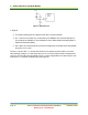
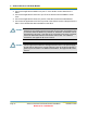
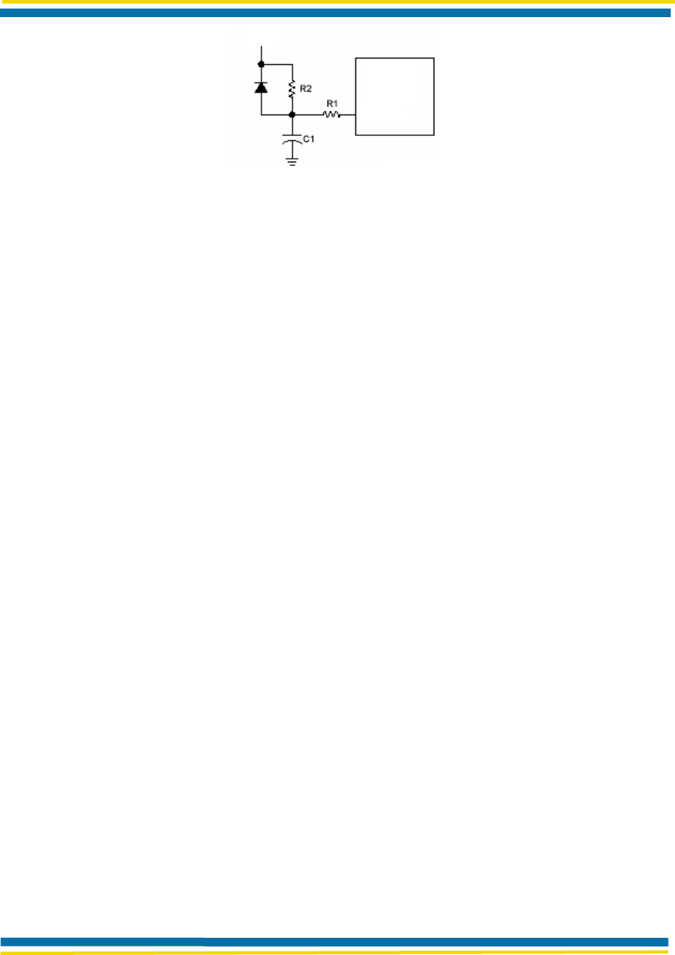
Figure 6. External Reset Circuit
In Figure 6:
The diode D discharges the capacitor when DV
DD
is powered down.
R1 = 100 Ω to 1K Ω limits any current flowing into /RESET from external capacitor C1.
This protects the /RESET pin from breakdown due to Electrostatic Discharge (ESD) or
Electrical Overstress (EOS).
R2 < 40K Ω is recommended to ensure that voltage drop across R2 leaves the /RESET
pin above a V
IHGP
level.
Choose C1 to have R2 ∞ C1 exceed five times the time period required for DV
DD
to reach a
valid operating voltage. V
DD
must start rising from V
ss
to ensure proper Power-On-Reset when
relying on the internal Power-On-Reset circuitry. If power supply takes more than 50 ms to rise
from 0 to 2.5 V, use RCs on /RESET pin (see Figure 6).
DV
dd
/RESET
A
irborne
WLN
Module