
Specifications


100-8004-102G Airborne Wireless LAN Node Module Data Book
Page 39
Quatech, Inc. Confidential
A.1 OVERVIEW
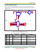
This appendix describes issues associated with external power switches and illustrates a circuit
for interfacing and controlling power to the Module from a 5 V system.
A.2 INTRODUCTION
Several applications, such as long-life battery-powered systems, require Wireless LAN Node
(WLN) functionality in a limited-power environment, where there are long intervals between
network accesses. When the system is inactive, an absolute minimum power draw from the
Module is required. Unfortunately, the Module’s low power modes are not always acceptable for
these systems.
Other systems have safety or other issues that require a guarantee that the system will not be
able to transmit. Since the Module’s IEEE 802.11 MAC is under firmware control, the only fail-
safe way to guarantee that the system cannot transmit is to disconnect the power.
Issues associated with powering-up systems may not be obvious. For example, the system is
held in reset until after the power supply stabilizes, but active systems only see stable power
supplies. Unexpected, even undesirable, actions can occur if power is applied to a capacitive
circuit. When power is applied, instantaneous inrush currents often exceed 2 amps, even in
small systems. Normally, this is not an issue at power-up; however, if a 5 Volt system, designed
to accommodate a 500-mA load, gets an instantaneous 2-amp load, the system voltage droops.
If this droop exceeds 500 mV, the system voltage exceeds specification and may cause errant
operation, and can even reset the system.
This appendix describes how to design a circuit to power the Module safely in a live 5 V system.
It addresses the requirements of the power supply and signal isolation, and the power
dissipation requirements for an industrial-temperature system.
A.3 LOAD HOT SWAPPING
To understand the problems associated with adding fairly large loads into an active system, it is
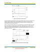
important to understand the characteristics of the inrush current. Figure 15 shows typical inrush
characteristics from the Module. The lower trace is the voltage drop across a 0.82-Ohm resistor
on the +5 V supply to the regulator. The upper trace is the Module’s +3.3 V supply. The peak
inrush current is I = (1.598)/(0.82) = 1.95 A. Adding the measurement resistor limits the inrush
current to some extent. In several cases, inrush currents exceeding 2.2 A have been measured.
APPENDIX A
POWER CONTROL