
Specifications


A – Power Control
100-8004-102G Airborne Wireless LAN Node Module Data Book
Page 41
Quatech, Inc. Confidential
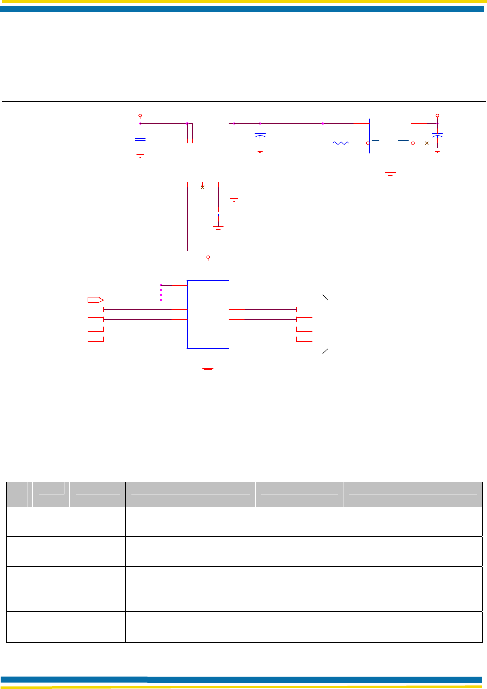
A.4 APPLICATION CIRCUIT
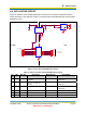
Figure 17 shows a recommended application circuit that can be used to obviate the harmful
effects described in this appendix. Table 17 shows the parts associated with the recommended
application circuit.
TXD
RTS
+3.3V CMOS OUT
+5.0V TOLERANT IN
+3.3V
#SHUTDOWN
Low ESR
Tantalum
RXD
CTS
MICREL
R1
10K,5%
Low ESR
Tantalum
+5.0V
NATIONAL
C2
22uF
C3
0.1uF
U1
MIC2505-1BM
5
7
6
8
1
2
4
3
IN1
IN2
OUT1
OUT2
CTL
FLG
GATE
GND
C1
22uF
C4
0.1uF
FAIRCHILD
CTS
RXD
SYSTEM
VR1 LP3871ES-3.3
2
1
4
5
3
VIN
SD
VOUT
ERR
GND
+5V
U2
FST3126
1
4
10
13
2
5
9
12
3
6
8
11
7 14
OE1
OE2
OE3
OE4
1A
2A
3A
4A
1B
2B
3B
4B
GND VCC
WLN
RTS
TXD
Figure 17. Recommended Application Circuit
Table 17. Parts List for Recommended Application Circuit
Ite
m
Qty. Ref. Des Description Manufacturer Part Number
1 2 C1, C2
Cap, 22 μF, 6.3 V, Tantalum,
Low ESR
AVX TPSB226M06#0600
or equivalent
2 2 C3, C4
Cap, 0.1 μF, 0603, 16 v,
Ceramic
Panasonic ECJ-1VF1C104Z
or equivalent
3 1 R1 Res, 10 K, 5%, 0603 Panasonic ERJ3GEYJ103#
or equivalent
4 1 U1 IC, High-side switch Micrel MIC2505-1BM
5 1 U2 IC, Bus Switch Fairchild FST3126
6 1 VR1 IC, Regulator National LP3871ES-3.3