
Specifications


A – Power Control
Page 42 Airborne Wireless LAN Node Module Data Book 100-8004-102G
Quatech, Inc. Confidential
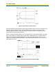
A.4.1 High-Side Switch
The Micrel high-side switch is a single-channel power switch with slow turn-on characteristics.
The device’s slow turn-on acts as an inrush current limiter and prevents large current spikes
from dropping the power supply rail.
Adding C4 (0.1 μF ceramic capacitor) on the GATE input of U1 slows the device’s switching
time. This slow turn-on of the switch, together with the internal current limiter of the MIC2505,
acts as a current limiter to prevent the full impact of the inrush on the system. The chosen value
of C4 sets the turn-on delay to approximately 375 ms.
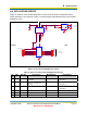
A.4.2 Voltage Regulator
The voltage regulator, VR1, is an ultra-fast low-drop-out linear regulator. The device’s high-
speed characteristics are essential for the fast load-changes the Module requires when
transmitting.
In this application, the regulator also provides a Power Supply Ripple Rejection Ratio (PSRR)
between the +5 V input and the +3.3 V output of 73 dB (typical). This further isolates the Module
transmitter and receiver from system noise.
It is important for the voltage regulator to have the proper input and output capacitors. The
National LP3871 requires a minimum of 10 μF for each of the input and output capacitors, while
the output capacitor requires an ESR of <5 Ω. When selecting an alternate voltage regulator,
pay attention to the input and output load requirements.
In an extremely power-limited application, a Switch Mode Power Supply (SMPS) is preferred
instead of the linear supply shown. The current linear regulator is approximately 66% efficient
(2.4 W input to 1.6 W output). An SMPS tuned for the application can be more than 80%
efficient, saving roughly 0.5 W that is currently being dissipated as heat in VR1.
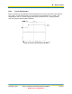
A.4.3 Bus Switch
The Bus Switch, U1, guarantees that no signal will be applied to the Module when the power
supply is shut down. Given the nature of CMOS input-protection devices (reverse-biased diodes
from the input to VCC and GND), any signal on the input conducts through the input protection
device onto VCC of the Module. While it may not provide enough current to operate the Module,
it may provide sufficient power to prevent proper initialization and startup of the Module when
power is applied.
While this circuit shows only the serial port signals (RXD, TXD, RTS, and CTS) being isolated,
all signals between the Module and the system must be isolated using a similar device.