
Specifications

C – WLN Ethernet Bridge
Page 48 Airborne Wireless LAN Node Module Data Book 100-8004-102G
Quatech, Inc. Confidential
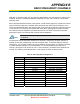
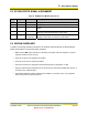
Table 20. WLN Module Ethernet-Specific Pin Assignments
WLN
Pin
WLN
Signal
Ethernet
Signal
Direction Description
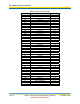
14 G4 RX- I Differential negative side input
13 G5 RX+ I Differential positive side input
32 E4 TXD+ O Differential positive side output with pre-emphasis
30 E5 TX+ O Differential positive side output
29 E6 TX- O Differential negative side output
31 E7 TXD- O Differential negative side output with pre-emphasis
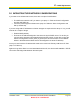
I/O lines G4 and G5 are used as digital inputs and may not exceed 2.4V.
I/O lines E4 – E7 are used as digital outputs with outputs not exceeding 3.3V.
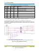
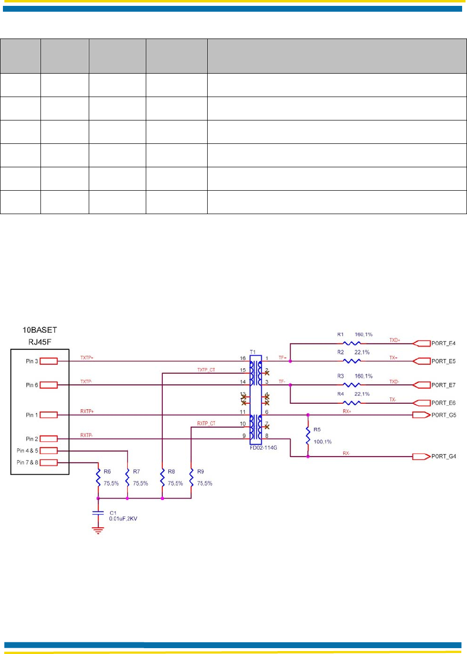
For proper interface with 10Base-T signals, it is recommended the I/O signals drive a
transformer/filter as indicated in the following schematic. The RJ-45F connector is for reference
and typically an embedded design will route the 10Base-T signals directly to the embedded host
Ethernet connections.
T1 – recommended transformer/filter: Halo FD02-114G
C1 – use lower voltage part when 10Base-T connections are not made to external connector.
Figure 19. Recommended Magnetics Schematic