AirborneDirect™ Ethernet Bridge User’s Guide PP T 802.11b/g ABDG-ET Series WLNG-ET Series T 802.11b ABDB-ET Series WLNB-ET Series Document number 100-8007-141G Quatech, Inc.
ALL RIGHTS RESERVED. No part of this publication may be copied in any form, by photocopy, microfilm, retrieval system, or by any other means now known or hereafter invented without the prior written permission of Quatech, Inc. This document may not be used as the basis for manufacture or sale of any items without the prior written consent of Quatech, Inc. AirborneDirect™ is a trademark of Quatech, Inc. All other trademarks used in this document are the property of their respective owners.
CONTENTS CHAPTER 1 INTRODUCTION................................................................................................................................1 TFEATURES AND BENEFITST ............................................................................................................................ 2 SAMPLE APPLICATION .................................................................................................................................. 3 TUSING THIS DOCUMENTT ..........................
Contents INDUSTRY CANADA NOTICE (APPLICABLE TO USE WITHIN CANADA) ............................................................. 60 AVIS DE CONFORMITE A LA REGLEMENTATION D’INDUSTRIE CANADA ............................................................ 61 INDUSTRY CANADA (IC) EMISSIONS COMPLIANCE STATEMENT..................................................................... 61 AVIS DE CONFORMITE A LA REGLEMENTATION D’INDUSTRIE CANADA ............................................................
Contents LIST OF FIGURES Figure 1. Basic Application Involving a LAN Host and Ethernet Client ........................................3 Figure 2. AirborneDirect™ Ethernet Bridge Hardware (standard package).................................9 Figure 3. Indicator LEDs on the AirborneDirect™ Ethernet Bridge............................................10 Figure 4. Mounting Cradle Dimensions......................................................................................12 Figure 5.
Contents LIST OF TABLES Table 1. AirborneDirect™ Ethernet Bridge Features and Benefits ..............................................2 Table 2. AirborneDirect™ Ethernet Bridge Indicator LEDs.......................................................11 Table 3. AirborneDirect™ Heavy-Duty Ethernet Bridge Indicator LEDs .....................................15 Table 4. Recording Information from Your Access Point’s Configuration Application ................20 Table 5. Miscellaneous OEM Settings ...................
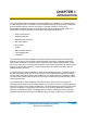
CHAPTER 1 INTRODUCTION This guide describes the AirborneDirect™ Ethernet Bridge from Quatech, Inc. AirborneDirect™ is a fully integrated, 802.11 wireless Local Area Network (LAN) connectivity device designed to provide wireless LAN and Internet connectivity in industrial, scientific, medical, and transportation applications where an existing communications interface already exists. The AirborneDirect™ Ethernet Bridge is well suited to the following applications: T Point-of-sale devices.
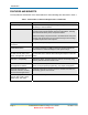
Introduction FEATURES AND BENEFITS T T The key features and benefits of the AirborneDirect™ Ethernet Bridge are described in Table 1. T TX XT T Table 1. AirborneDirect™ Ethernet Bridge Features and Benefits Feature Small package outline T Benefit Easy to attach to existing equipment; light enough to allow easy mounting to vertical surfaces.
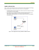
Introduction SAMPLE APPLICATION Figure 1 shows a basic application where the AirborneDirect™ Ethernet Bridge is exchanging data wirelessly between an Ethernet client and a LAN host. In this application: X X T The Ethernet client can be any device with an Ethernet port that is directly connected to the AirborneDirect™ Ethernet Bridge. T T T T The LAN host can be a network-based PC or server that requires connection to the Ethernet Client using the network.
Introduction USING THIS DOCUMENT T T In addition to this chapter, this guide contains the following chapters and appendixes: Chapter 2, Hardware Installation ⎯ describes the AirborneDirect™ Ethernet Bridge hardware and how to install it.
Introduction CONVENTIONS The following conventions are used in this guide: Terminology T In the following chapters, these terms are used: “AirborneDirect™ Ethernet Bridge” is used the first time the Bridge is mentioned in a chapter. Thereafter, the term “Bridge” is used. “Ethernet client” refers to the device to which the AirborneDirect™ Ethernet Bridge is connected and which communicates with the Bridge over an RJ-45 connection.
Introduction RELATED DOCUMENTATION In addition to this guide, the following documents are provided on the CD supplied with the AirborneDirect™ Ethernet Bridge: AirborneDirect™ Ethernet Bridge User’s Guide. T AirborneDirect™ Ethernet Bridge Quick Start Guide. T Product Briefs and Application Notes. T These documents are provided as Portable Document Format (PDF) files. To read them, you need Adobe® Acrobat® Reader® 4.0.5 or higher.
CHAPTER 2 HARDWARE INSTALLATION This chapter describes the AirborneDirect™ Ethernet Bridge. Topics in this chapter include: T T Package Contents. (below) T Items Supplied by the User. (below) T Hardware Description. (page 9) T X X Selecting a Location. (page 13) T X X Configuring The Access Point. (page 16) T X X Connecting the Bridge. (page 17) T T X X Verifying Your Connections.
Hardware Installation ITEMS SUPPLIED BY THE USER T The following items, which are not included in the package contents, are also required: T An Ethernet client, with an RJ-45 jack, that is within the transmit and receive range of the Access Point to be used with the Bridge. T A LAN host running any operating system with TCP/IP (the ACC requires Microsoft® Windows® XP or Windows 2000). T P P P P An IEEE 802.11b/g-compliant Access Point with DHCP enabled.
Hardware Installation STANDARD PACKAGE HARDWARE DESCRIPTION X Figure 2 identifies the components on the Bridge in its standard packaging. These components include: X X An external antenna. An RJ-45 jack and cable attached to the Bridge. A Reset switch on the bottom of the Bridge. Three indicator Light Emitting Diodes (LEDs) on the top of the Bridge. A mounting cradle. Figure 2.
Hardware Installation Indicator LEDs The Bridge has three indicator LEDs for viewing its current status and its connections (see Figure 3). These indicators allow for monitoring and troubleshooting of the Bridge. They also indicate the Bridge’s power-up status, link, connection, and data-activity status. Table 2 describes the status of the indicator LEDs. X X X X Figure 3. Indicator LEDs on the AirborneDirect™ Ethernet Bridge Page 10 AirborneDirect™ Ethernet Bridge User's Guide Quatech, Inc.
Hardware Installation Table 2. AirborneDirect™ Ethernet Bridge Indicator LEDs LED Power Link Comm LED Color Off Function Bridge is not receiving power. Red Bridge failed its Power On Self Test (POST) and is not configured for wireless communication. Amber Bridge passed its POST but is not configured for wireless communication. Green Bridge passed its POST and is configured for wireless communication. Off Bridge is not receiving power. Blinking Red Bridge is searching for an Access Point.
Hardware Installation Mounting Cradle The Bridge comes with a mounting cradle that allows the Bridge to be installed on a vertical surface, such as a wall (see Figure 4). Be careful not to tighten the mounting hardware (usersupplied) excessively to avoid damaging the cradle. When mounting the Bridge vertically, attach the cradle to the vertical surface, and then insert the Bridge into the cradle. X X Figure 4.
Hardware Installation HEAVY-DUTY PACKAGE The heavy-duty version of the Bridge is supplied in a Deutsch EEC-325X4B enclosure and is available in both sealed and unsealed versions. The heavy-duty Bridge supports SAE J1455 power specifications (+4.5 to 36 VDC). Figure 5 identifies the components on the Bridge in its heavy-duty packaging. These components include: An external antenna. A Deutsch 12-pin DTM13-12PA-R008 receptacle for power and signal connections. A Reset switch.
Hardware Installation Figure 6. AirborneDirect™ Heavy-Duty Cable (Evaluation Kit Item) Page 14 AirborneDirect™ Ethernet Bridge User's Guide Quatech, Inc.
Hardware Installation Indicator LEDs The Heavy-Duty Bridge has four indicator LEDs for viewing its current status and connections (see Figure 5). These indicators allow for monitoring and troubleshooting of the Bridge. They also indicate the Bridge’s power-up status, link, connection, and data-activity status. Table 3 describes the status of the indicator LEDs. Table 3.
Hardware Installation SELECTING A LOCATION You can mount the Bridge on a flat surface, such as a desk or table, or on a vertical surface, such as a wall. It can also be mounted on the ceiling. If you mount the Bridge vertically, use the supplied mounting cradle previously described. Choosing a good location for the Bridge is important because it affects the reliability of the wireless link. The most important considerations are distance from the Access Point and clearance from obstacles.
Hardware Installation CONNECTING THE BRIDGE The following procedure describes how to connect the Bridge: • Place the Bridge in a dry, clean location near the device to which it will be connected. The location is required to have an AC power source and be within 300 feet (100 meters) of an IEEE 802.11b/g-compliant wireless LAN Access Point with DHCP enabled.
Hardware Installation This page intentionally left blank. Page 18 AirborneDirect™ Ethernet Bridge User's Guide Quatech, Inc.
CHAPTER 3 INITIAL CONFIGURATION This chapter describes configuring the AirborneDirect™ Ethernet Bridge. Topics in this chapter include: Wireless Configuration. (below) Verifying Your Connections (page 20) WPA-LEAP Security. (page 20) WIRELESS CONFIGURATION After you verify that the indicator LEDs have gone through their power-up sequence, start the configuration application for your Access Point (your Access Point manual should describe this procedure).
Initial Configuration If you do not see the Bridge as an attached device, refresh the configuration Note: screen (some Access Point programs provide a Refresh button for this purpose). If the Bridge still does not appear, refer to the troubleshooting chapter in this Guide and in the documentation for your Access Point. Note: You can also use the device discovery feature of the Airborne Control Center software (see page 25) to help determine the Bridge’s IP address.
Initial Configuration VERIFYING YOUR CONNECTIONS When the Bridge is powered-up, the indicator LEDs at the top of the Bridge will indicate the status of the Bridge. See Table 2 on page 11 for standard packaging, or Table 3 on page 15 for Heavy-Duty packaging. If the LEDs indicate a problem with a wired or wireless connection, remove the power source from the Bridge, wait a few seconds, and re-apply power. If the LEDs still do not behave appropriately, see the guidelines in Table 11 on page 52.
Initial Configuration WPA-LEAP SECURITY The WPA and LEAP software modules provide advanced security configuration and communication services required by today’s enterprise-class deployments. Please refer to IEEE standard 802.1x 2001 (section 4) and IEEE standard 802.11i 2004 (section 4) for additional information. System Requirements Both WPA and LEAP require radio firmware version 1.1.1.111.8.4 or later. The AP requires WPA support. LEAP must be supported in the AP or a separate authentication server.
Initial Configuration The Link LED turns green when 802.11 association completes. However, if the 802.1x authentication fails, the bridge becomes disassociated by the AP and the Link LED goes back to flashing red. The bridge will not respond to discovery requests. Once the bridge is authenticated, additional impacts include: Roaming A bridge configured for WPA-PSK can only roam to APs that have WPA-PSK enabled in the same ESS.
Initial Configuration This page intentionally left blank. Page 24 AirborneDirect™ Ethernet Bridge User's Guide Quatech, Inc.
CHAPTER 4 AIRBORNE CONTROL CENTER This chapter describes how to use the Airborne Control Center (ACC) to configure the AirborneDirect™ Ethernet Bridge. The ACC is a user-friendly graphical-user interface (GUI) menu and data display. The interface is intuitive, allowing tasks to be performed simply by pointing and clicking your mouse. LAUNCHING THE ACC On the Windows XP Start menu, navigate to the Quatech submenu and click on Airborne Control Center.
Airborne Control Center Figure 9. Device login The IP address and telnet port number of the selected device are automatically transferred to the login page. Enter the user name and password (defaults “dpac” and “dpac”) and click on the OK button to login. To select a different device, click the Discover button to reinitiate the device detection scan. The Status page is displayed as shown in Figure 7. X X Figure 10. Status Page Page 26 AirborneDirect™ Ethernet Bridge User's Guide Quatech, Inc.
Airborne Control Center NAVIGATING AROUND THE ACC A navigation bar appears at the top-right side of every screen in the ACC interface (see Figure 8). This bar contains links that correspond to the pages you can access. To go to a page, click the appropriate link in the navigation bar. X X Figure 11. ACC Navigation Bar PERFORMING CONFIGURATION ACTIVITIES The ACC allows you to perform a variety of configuration activities. Basic configuration activities consist of the following steps.
Airborne Control Center Advanced configuration activities consist of the following: Changing the user name and administrator password Lets you change the user name and administrator password for accessing the configuration interface. See “Security Settings Page” on page 43. X X X X X X X Resetting the Bridge Lets you reset the Bridge to the factory-default settings. See “Reset Page” on page 48.
Airborne Control Center SAVING CONFIGURATION CHANGES Some pages have Save and Cancel buttons. If you change parameters on one of these pages, click Save to apply your changes or Cancel to discard them. Once the changes are saved, the ACC displays the screen shown in Figure 9. To continue, click Yes, or you can go to another page to make more changes then click Restart to apply all the changes at one time. X X The ACC will display Figure 10. Wait for the Restart to complete.
Airborne Control Center BASIC CONFIGURATION SETTINGS Status Page (Basic Configuration Settings) Figure 14. Status Page The Status Page is the first page that appears in the ACC. This read-only page shows information about the Bridge. You may need to click the Status button in the navigation bar to update the contents on this page. This page shows the Bridge’s version number, 802.11 status, network settings, and resources.
Airborne Control Center Miscellaneous Settings Page (Basic Configuration Settings) Figure 15. Miscellaneous OEM Settings Page Clicking the Misc link in the navigation bar displays the Miscellaneous OEM Settings page. In this page, you can enter the Bridge’s OEM version string and discovery name. This page also lets you specify the OEM user name and password. 100-8007-141G AirborneDirect™ Ethernet Bridge User's Guide Quatech, Inc.
Airborne Control Center Table 5. Miscellaneous OEM Settings Parameter Description Miscellaneous OEM Settings OEM Version String Specifies the OEM version string to be associated with the Bridge. Default is oemverstr. OEM Discovery Name Specifies the OEM discovery name to be associated with the Bridge. Default is OEM-Cfg1. OEM Authentication Settings OEM User Name Specifies the name of the OEM, from 1 to 31 alphanumeric characters. Name is case-sensitive. Default is oem.
Airborne Control Center Network Settings Page (Basic Configuration Settings) The Network Settings Page allows you to modify the 802.11 wireless network settings, including network identification, security, data rate, and discovery name. You are also able to set Network IP settings for control of the wired LAN, including enabling DHCP, static IP address and associated network settings. This page actually displays more than one page of information.
Airborne Control Center Figure 13. Wireless Network Configuration Page (continued) X X Figure 13. Wireless Network Configuration Page (continued) X Page 34 X AirborneDirect™ Ethernet Bridge User's Guide Quatech, Inc.
Airborne Control Center Table 6. Wireless Network Configuration Settings Parameter Description Wireless Network Settings SSID Service Set Identifier that identifies the common service set for the Bridge and AP. To make this connection, the Bridge and AP must have the same SSID. Default setting is any (this field may not be blank). Wireless Network Type Specifies the type of network in which the Bridge will be used: • Infrastructure – connects to a WLAN using an AP.
Airborne Control Center Wireless Security Settings Enables or disables wireless security: Wireless Security Mode • Disable – Disable any security (default) • WEP64 – 64-bit key length (11 ASCII characters) • WEP128 – 128-bit key length (26 ASCII characters) • WPA-PSK - WPA with preshared key. Requires preshared key • WPA-LEAP - WPA with 802.1x (LEAP) • WPA-LEAP64 • WPA-LEAP128 - WPA with 802.
Airborne Control Center LEAP Password Configures the WPA-LEAP password. The LEAP password [1 to 32 characters] must match the LEAP password assigned to the LEAP user on the LEAP server. The LEAP password cannot contain spaces.
Airborne Control Center Maximum Transmission Rate Bridge’s maximum wireless transmission rate. The Bridge will attempt the highest specified rate and fallback to a lower rate if necessary. Default is 5.5 Mbps. Network IP Settings Enable DHCP Client When checked, enables the Dynamic Host Configuration Protocol (DHCP). For this parameter to work, the AP or network must support DHCP. DHCP Client Name Bridge’s DHCP client name. Enable DHCP Fixed Interval Retransmission Enables the interval value below.
Airborne Control Center Configures the Subnet Mask used by the DHCP fallback algorithm. DHCP Fallback Subnet Default is 255.255.255.0 Configures the gateway address used by the DHCP fallback algorithm. DHCP Fallback Gateway Default is 0.0.0.0. Static IP Address If you use a static IP, each Bridge must have a unique IP address. The IP address must adhere to the network’s subnet mask and fall within the valid range of IP addresses for the network.
Airborne Control Center Table 7.
Airborne Control Center ADVANCED CONFIGURATION SETTINGS Services Page (Advanced Configuration Settings) The Services Page lets you configure the Bridge’s network services like Telnet and TCP Port settings. Figure 17. Network Services Page 100-8007-141G AirborneDirect™ Ethernet Bridge User's Guide Quatech, Inc.
Airborne Control Center Table 8. Network Services Settings Parameter Description Enable UDAP When checked, enables Universal Data Appliance Protocol (UDAP). This allows the Bridge to be discovered from a LAN-based device that supports the UDAP protocol. Default is checked. Telnet Port Specifies the port number of the Telnet server. Default is 23. Telnet Inactivity Timeout – seconds Specifies the number of seconds of inactivity that must occur for the Telnet session to timeout.
Airborne Control Center Security Settings Page (Advanced Configuration Setting) The Security Settings Page allows management of the authentication-based access services. You can change user names and passwords. Figure 18. Security Configuration Page 100-8007-141G AirborneDirect™ Ethernet Bridge User's Guide Quatech, Inc.
Airborne Control Center Table 9. Security Configuration Settings Parameter Description Configuration User Name Specifies the user name required to log into the Bridge’s configuration interface, from 1 to 31 alphanumeric characters. User name is case-sensitive. Default is cfg. If you change it, you are prompted for the user name and password at the next transaction (for example, when you move to another page or refresh the current page).
Airborne Control Center Update Firmware Page (Advanced Configuration Settings) The Update Firmware Page allows you to update the firmware running on the AirborneDirect™ Ethernet Bridge. Updating firmware may cause the Bridge to stop operating if it is not Caution: performed properly. Only advanced users should update firmware. If you encounter problems, contact Quatech, Inc. Figure 19. Update Firmware Page 100-8007-141G AirborneDirect™ Ethernet Bridge User's Guide Quatech, Inc.
Airborne Control Center The firmware must come from Quatech, Inc. as a .bin file and follow the file name format: DirectEthernet_ x.x.x.x.bin Note: Where xxxx is the version number of the firmware. For example: DirectEthernet_4.2.0.12.bin Do not attempt to load firmware for an 802.11b/g bridge on an 802.11b Caution: bridge or vice-versa. T T To update the firmware, the following sequence must be performed: • Select the Update link on the ACC screen.
Airborne Control Center • The ACC will display the message shown in Figure 18. X X Figure 21. Update Complete Message • Upon restarting, the Status Page will be displayed. If this does not happen automatically, close the ACC and restart it. Caution: Updating firmware may cause loss of saved parameters. 100-8007-141G AirborneDirect™ Ethernet Bridge User's Guide Quatech, Inc.
Airborne Control Center Reset Page (Advanced Configuration Settings) The Reset Page allows you restart or reset the Bridge to the factory default values. Resetting the AirborneDirect™ unit to factory defaults will remove all Caution: customer changes. If the target AP has WEP or WPA enabled, the AirborneDirect™ unit will not be able to associate (WEP/WPA default is disabled). Figure 22. Reset Page Page 48 AirborneDirect™ Ethernet Bridge User's Guide Quatech, Inc.
Airborne Control Center Restarting the Bridge When you click the Restart button, you will see the Warning displayed in Figure 20. Click Yes to complete the Bridge restart or No to stop the process and return to the Reset Page. X X Figure 23. Confirm Restart Figure 21 will be displayed after you have clicked Yes. Click OK to dismiss this informational dialog. Once the restart has been completed, the ACC will display the Status Page. X X Figure 24.
CHAPTER 5 TROUBLESHOOTING This chapter provides troubleshooting suggestions you can follow in the unlikely event you encounter a problem using the AirborneDirect™ Ethernet Bridge. TROUBLESHOOTING SUGGESTIONS Table 10. Troubleshooting Suggestions The Bridge cannot find the Access Point. Verify that the Link LED is solid green. If it isn’t, refer to “LED Troubleshooting” on the next page. The Access Point cannot find the Bridge. Click the Refresh button in your Access Point’s configuration application.
Troubleshooting After changing the Bridge’s static IP address, the ACC stops responding. Once the static IP address is changed and you click Save, the Bridge switches to the new IP address and loses connection with the ACC. To resolve this problem, restart the ACC. You used the ACC to change the Bridge’s configuration settings, but the new settings did not take effect. You may not have clicked the Save button on the ACC page. Click this button after making your changes on the page.
Troubleshooting LED TROUBLESHOOTING The following table provides LED troubleshooting suggestions. Table 11. Indicator LED Troubleshooting If the… Perform These Tasks… Power LED does not turn On. Check power connector is properly inserted. Power LED turns Red. Remove power and re-apply. If the Power LED remains Red, contact Quatech, Inc. Power LED is Amber. Bridge has not established an IP address either through DHCP or Static methods.
APPENDIX A SPECIFICATIONS This appendix lists the specifications of the AirborneDirect™ Ethernet Bridge. Table 12. Specifications Ethernet Interface – standard package Interface: Ethernet 10Base-T Connector: RJ-45 Flexible, stranded, copper conductor cable Data Rates: 100-8007-141G 10 Mb/sec AirborneDirect™ Ethernet Bridge User's Guide Quatech, Inc.
Specifications Ethernet Interface – Heavy-Duty package Interface: Ethernet 10Base-T Connector: Deutsch DTM-06-12SSA Data Rates: 10 Mb/sec Pin Assignments: Pin No. Name Description 1 TXTP+ Transmit+ 2 RXTP+ Receive+ 3 NC No Connect 4 NC No Connect 5 ON/IGN Device power OBN. Active High (internal pull-down). Default ON Pulling signal LOW shuts off the internal power supply. 6 VBAT Battery Power Input 7 GND Ground 8 /F_RESET Factory RESET. Active LOW (internal pull-up).
Specifications Wireless Network Interface Interface (ABDB, WLNB): IEEE 802.11b DSSS, WiFi compliant (ABDG, WLNG): IEEE 802.11b/g, WiFi compliant (802.11i, 802.11e, 802.11d capable) Frequency: 2.4 ~ 2.4835 GHz (US, Europe, Canada, Japan) 2.471 ~ 2.497 GHz (Japan) Channels: 11 US/Canada 13 Europe 14 Japan 4 France Data Rates (ABDB, WLNB): 11, 5.5, 2, 1 Mbps (ABDG, WLNG): 802.11b mode: 11, 5.5, 2, 1 Mbps 802.
Specifications Indicators Power, Link, Comm LEDs (standard): Post, Cfg, Link, Conn LEDs (heavy-duty): Power (See Table 13 for Heavy-Duty) Input: 110/240 V, 50-60 Hz, external power supply wall wart Consumption: 2 W max (AC Adaptor) Power Supply Connector: 2.
Specifications Standard Packaging Enclosure: Nylon – Grey Dimensions: 2.58 in. W x 4.03 in. L x 1.90 in. D (65.5 mm x 102.3 mm x 48.2 mm) Heavy-Duty Packaging Enclosure: Plastic Dimensions: 4.63 in. W x 5.24 in. L x 1.43 in. D (117.6 mm x 133.0 mm x 36.2 mm) 100-8007-141G AirborneDirect™ Ethernet Bridge User's Guide Quatech, Inc.
Specifications Table 13 and Table 14 list power supply specifications for the Heavy-Duty Bridge. The standard package Bridge is powered by the included AC adapter. Table 13 Note: and Table 14 do not apply to the standard package. Table 13. Heavy-Duty Power Supply Specifications Parameter Min Max Normal Operating (J1455 – 12 V system) 9V 16V Normal Operating (J1455 – 24 V system) 18V 32V Cold Cranking (J1211) 4.
APPENDIX B FCC COMPLIANCE This appendix lists FCC compliance information for the AirborneDirect™ Ethernet Bridge. FCC STATEMENT This equipment has been tested and found to comply with the limits for a Class B digital device, pursuant to Part 15 of the FCC Rules. These limits are designed to provide reasonable protection against harmful interference in a residential installation.
FCC Compliance MANUFACTURER’S DECLARATION OF CONFORMITY Trade Name: AirborneDirect™ Serial Bridge AirborneDirect™ Ethernet Bridge Airborne Embedded Radio Module Model Number: ABDB-SE-DP101 ABDB-ET-DP101 WLRG-RA-DP101 Compliance Test Report Number: B31211D3 F4AWLNG1 Compliance Test Report Date: December 11, 2003 July 17, 2006 Responsible Party (in USA): Address: Quatech, Inc.
FCC Compliance AVIS DE CONFORMITE A LA REGLEMENTATION D’INDUSTRIE CANADA Pour empêcher toute interférence aux services faisant l’objet d’une licence, cet appareil doit être utilisé à l’intérieur seulement et devrait être placé loin des fenêtres afin de fournir un écran de blindage maximal.
FCC Compliance indicates that usage restrictions apply. To ensure compliance with local regulations, be sure to select the country in which the access point is installed.
FCC Compliance Countries Dutch French Danish German Swedish Greek Italian Spanish Portuguese 100-8007-141G Restrictions Hierbij verklaart DPAC Technologies Corp. dat het toestel AirborneDirect™ Serial/Ethernet Bridge in overeenstemming is met de essentiële eisen en de andere relevante bepalingen van richtlijn 1999/5/EG. Bij deze verklaart DPAC Technologies Corp.
FCC Compliance This page intentionally left blank. Page 64 AirborneDirect™ Ethernet Bridge User's Guide Quatech, Inc.
GLOSSARY This appendix provides a glossary of wireless terminology. 802.11 Wireless standards developed by the IEEE that specify an "over-the-air" interface for wireless Local Area Networks. 802.11 is composed of several standards operating in different radio frequencies. 802.11b 802.11b is the international standard for wireless networking that operates in the 2.4 GHz frequency range (2.4 GHz to 2.4835 GHz) and provides a throughput of up to 11 Mbps. 802.11g 802.
Glossary Disassociation service An IEEE 802.11 term that defines the process a station or Access Point uses to notify that it is terminating an existing association. Distribution service An IEEE 802.11 station uses the distribution service to send MAC frames across a distribution system. GPIO General Purpose Input/Output refers to the digital I/O lines. Hot spot Same as an Access Point (usually found in public areas such as coffee shops and airports).
Glossary RTOS An operating system implementing components and services that explicitly offer deterministic responses, and therefore allow the creation of real-time systems. An RTOS is characterized by the richness of the services it provides, the performance characteristics of those services, and the degree that those performance characteristics can be controlled by the application engineer (to satisfy the requirements of the application).
Glossary This page intentionally left blank Page 68 AirborneDirect™ Ethernet Bridge User's Guide Quatech, Inc.
INDEX A I Accessing the Web interface, 25 Advanced Configuration Settings, 41 AirborneDirect Ethernet Bridge features and benefits, 2 hardware description, 9 installation, 17 LEDs, 10 package contents, 7 reset switch, 9 sample application, 3 AirborneDirect Serial Client Bridge LEDs, 15 Application, 3 Applications, 1 B LED troubleshooting, 52 LEDs, 10, 15 Location selection, 16 M Miscellaneous Settings Page, 31 Mounting cradle, 12 Navigating through the Web interface, 27 Network Settings page, 33 C CL
Index U Update Firmware Page, 45 Using This Document, 4 V VERIFYING YOUR CONNECTIONS, 21 accessing, 25 configuration activities, 27 navigating through, 27 Web interface pages Network Settings, 33 Reset, 48 Services Page, 41 Status, 30 WPA-LEAP Security, 19, 22 W Web interface Page 70 AirborneDirect™ Ethernet Bridge User's Guide Quatech, Inc.
100-8007-141G Revision 1.