
Specifications


Quatech, Inc. Airborne DP550 Family Databook
32 4/14/2011 100-8090-100
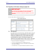
10.0 Mechanical Outline
Figure 6 – DP550 Mechanical Outline
26.20mm
13.10mm
2.00mm
20.30mm
14.80mm
15.90mm
5.80mm
+0.25mm
-0.20mm
3.80mm
CN1
CN3
CN2
Ø5.00mm
Dimensions: mm
Tolerance: ± 0.15 (unless noted)
29.60mm
40.60mm
17.00mm17.00mm
SIDE VIEW
36
35
2
1
2.25mm±0.10mm
Hirose U.FL
Hirose U.FL
Hirose DF12-36DS-0.5V
2.25mm±0.10mm
2.50mm
1.00mm
1.57mm±0.10mm
21.00mm
32.00mm
16.00mm
10.50mm
TOP VIEWBOTTOM VIEW
Module Connector: DF12B-36DS-0.5V(XX) (Hirose)
Hirose: 0.50mm (.020") Pitch Plug, Surface Mount, Dual Row, Vertical, 4.00mm
Stack Height, 36 Circuits
Board Connector: DF12(4.0)-36DP-0.5V(XX) (Hirose)
Hirose: 0.50mm (.020") Pitch Plug, Surface Mount, Dual Row, Vertical, 4.00mm
Stack Height, 36 Circuits
RF Connector: U.FL
Hirose: Ultra Small Surface Mount Coaxial Connector
The mounting hardware for the DP550 device utilizes a friction fit for retention of the thru-hole
pins to the host board.
To support this configuration the maximum diameter of the thru-hole pin is 2.8mm. Although
this exceeds the recommended mounting hole size (see section 11.1), the pin diameter is
compliant and will compress to fit the recommended hole diameter.