MODBUS™ RTU Communications Guide for use with MODCELL, MOD 30ML and Commander Products
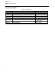
MODBUS RTU CONTENTS CONTENTS Page OVERVIEW ......................................................................................................................................................... 1 HARDWARE REQUIREMENTS.......................................................................................................................... 2 SERIAL INTERFACE CONSIDERATIONS .................................................................................................... 2 CABLE REQUIREMENTS ............
MODBUS RTU CONTENTS TABLES Page Table 1. Cable Requirements .............................................................................................................................2 Table 2. Instrument Response Times .................................................................................................................5 Table 3. Software Drivers....................................................................................................................................6 Table 4.
MODBUS RTU COMUNICATIONS GUIDE OVERVIEW MODBUS RTU is a non-proprietary serial communications protocol that is widely used in the process control industry. The protocol was developed by Modicon for PLC communications and later released for public use. This protocol is available in all major Human Machine Interface (HMI) software packages and terminals. Many of the major controller and PLC manufacturers also offer MODBUS protocol as a standard or optional protocol in their instrumentation.
MODBUS RTU COMUNICATIONS GUIDE HARDWARE REQUIREMENTS SERIAL INTERFACE CONSIDERATIONS The Modbus protocol communicates with the instrumentation by means of an industry standard serial interface. This interface may be RS-232, RS-422 or RS-485. Some systems may also support the protocol over other busses or networks, such as Ethernet. An RS-232 interface allows only two devices to be connected together. RS-422 supports 1 driver and up to 10 receivers on a single network.
MODBUS RTU COMUNICATIONS GUIDE RS-232 INTERFACE An RS-232 interface is rated for distances up to 15 meters (50 feet). At least three wires are required for an RS-232 interface. Wires are required for Transmit, Receive and Signal Ground. Some devices support additional wires for communication handshaking. RS-232 hardware is a full-duplex configuration, having separate Transmit and Receive lines. RS-422 INTERFACE An RS-422 interface requires at least four wires.
MODBUS RTU COMUNICATIONS GUIDE 2-Wire Configuration 4-Wire Configuration Figure 1.
MODBUS RTU COMUNICATIONS GUIDE SOFTWARE BASICS MASTER/SLAVE RELATIONSHIP A MODBUS RTU system consists of a Master and one or more Slave devices. Multiple Masters are not permitted on the same network. The Master is responsible for initiating all communications, therefore, no peer-to-peer capability is supported. With some hardware, it is possible to dynamically switch the device between Master and Slave modes. This capability allows multiple Masters, though not simultaneously.
MODBUS RTU COMUNICATIONS GUIDE SOFTWARE DRIVERS Table 3. Software Drivers 6 Driver 1719S 1733S 2010S 2011S I/O Server DDE Server OPC Server Description Standard MODBUS Driver Extended MODBUS Driver EMP 16-bit Standard and Extended MODBUS Driver EMP 32-bit Standard and Extended MODBUS Driver Standard MODBUS Standard MODBUS Standard and Extended MODBUS MODCELL MODBUS Enhanced Standard MODBUS Standard MODBUS Use With PC-30 and GFW PC-30 and GFW FIX 5.x for Windows 3.x FIX 6.
MODBUS RTU COMUNICATIONS GUIDE MODBUS WITH MODCELL MLP AND MOD30ML STANDARD PROTOCOL “Standard” MODBUS supports single-register, 16-bit integer values. Modcell and MOD30ML floating-point data may be converted to this format with ML blocks. For maximum resolution, specify an actual engineeringunit range in the ML block. If the engineering range is greater than 65535, a scaled range must be selected.
MODBUS RTU COMUNICATIONS GUIDE USING ML AND CL BLOCKS: DIRECTING DATA WITH ML AND CL BLOCKS CL blocks can be connected to MSC blocks, and are usually used for discrete points. A CL block is required for multi-register “standard” MODBUS functions, such as those needed for floating point signals. If a floating point value is placed into an ML block, it is converted to a 16-bit integer value to be sent to the host.
MODBUS RTU COMUNICATIONS GUIDE BLOCK CONNECTIONS (Up to 99 Inputs per Block) Figure 3.
MODBUS RTU COMUNICATIONS GUIDE USING MODBUS MODULES: MODULE LOCATION The sockets in which the module is installed determines its Port number Table 4.
MODBUS RTU COMUNICATIONS GUIDE COMM RS232 CAT. NO. 2033NZ10000A YES COMM DEFAULTS NO COMM RS485 T E R M * NOTE: CAT. NO. 2034NZ10000A YES NO HIGH LOW YES COMM DEFAULTS HIGH LOW NO Address is indicated with the flat side of the switch Figure 4.
MODBUS RTU COMUNICATIONS GUIDE MODBUS MASTER MASTER REQUIREMENTS MODBUS Master communication requires a few special configuration items. 1. MSC Block - Each MSC block that will be used for MODBUS Master communications must have the Port Functionality set to Master. 2. EX Block for Port Configuration - Each MODBUS Master port requires a specially configured Expression block to define its parameters. 3.
MODBUS RTU COMUNICATIONS GUIDE INPUT CONVERT BLOCK One expression block is required for each analog value read from the slave instrument, for data type conversion. The expression is as follows: if Input > 32767 then (Input - 65536.0) / Scaler else Input / Scaler Input is a COUNT value which is read from the slave instrument. Scaler is the FLOATING-POINT result of the Scaler block.
MODBUS RTU COMUNICATIONS GUIDE MODBUS WITH COMMANDER SERIES INSTRUMENTS SCALING ANALOG VALUES The first Commander instruments to support MODBUS handled scaling of analog values in a different way than later instruments. The C200, C300, C1900 and PR100 use a 12-bit register with a raw range of 0 to 4095. The host must scale the value to obtain the desired engineering unit value. Newer models, such as the C100, C150, C250, C500 and PR250, place an engineering unit value into one or two 16-bit registers.
MODBUS RTU COMUNICATIONS GUIDE HOST CONFIGURATION EXAMPLES MODBUS WITH FIX AND COMMANDER 150 Either the MB1 or EMP driver may be used, though EMP is recommended. The MODBUS guide uses 1 and 2-digit numbers for addresses. Note that the actual addressing requires a 5-digit number. For digital addresses, use 000xx format, where xx represents the coil address from the instruction book. For analog addresses, use 400xx format, where xx represents the register address from the instruction book. Table 6.
MODBUS RTU COMUNICATIONS GUIDE MODBUS WITH FIX AND COMMANDER 300 Either the MB1 or EMP driver may be used, though EMP is recommended. The MODBUS guide uses 3-digit numbers for addresses. Note that the actual addressing requires a 5-digit number. For digital addresses, use 00xxx format, where xxx represents the coil address from the instruction book. For analog addresses, use 40xxx format, where xxx represents the register address from the instruction book. Table 7.
MODBUS RTU COMUNICATIONS GUIDE MODBUS WITH INTOUCH AND COMMANDER 300 Below are configuration entries that have been tested with the InTouch Modbus DDE Server and C300. Table 8. MODBUS with InTouch and Commander 300 Hardware String Variable Style Register Type Block I/O Sizes Coil Read - 16 Coil Write* - 8 * NOTE: 584/984 PLC Full Length Binary Register Read - 8 Register Write - 8 The Commander supports only Single-Coil writes (Function Code 05), so Block I/O does not apply.
MODBUS RTU COMUNICATIONS GUIDE MODCELL MLP WITH TCP QUICKPANEL Table 9. Wiring for RS-485 Full Duplex QuickPanel jr.
MODBUS RTU COMUNICATIONS GUIDE Scaling In ML Block, specify actual range for variable, if the number of significant digits is 5 or less. For ranges with more than 7 significant digits, such as 500,000 or 750.000, change the units to allow smaller numbers. For example, instead of 0 to 500,000 CFH, use 0 to 500 KCFH. Also note that the scale factor is for use only with mSec time values. The field is enabled for sources that can support the data type.
MODBUS RTU COMMUNICATIONS GUIDE MOD30ML AND MODCELL MLP REFERENCE TABLES Table 11.
MODBUS RTU COMMUNICATIONS GUIDE Table 12.
MODBUS RTU COMMUNICATIONS GUIDE WIRE CONNECTIONS Table 13. Wire Connections for RS-232 Devices PC Serial Port 25-Pin 9-Pin 2 3 7 3 2 5 MOD30ML Port 1 Port 2 BI 9&10 7&8 3 9 13 2 8 12 1 10 14 Mod cell MLP Hi-1 Hi-2 Lo-2 RS-232 Master ⇒ Tx ⇐ Rx Gnd ⇔ Slave Rx Tx Gnd MOD30ML Port 1 Port 2 BI 9&10 7&8 2 8 12 3 9 13 1 10 14 Modcell MLP Hi-2 Hi-1 Lo-2 Table 14.
MODBUS RTU COMMUNICATIONS GUIDE MODBUS MODULE TROUBLESHOOTING WITH MOD30ML AND MODCELL MLP * NOTE: The extended Modbus communications required for diagnostics and downloading is supported by the 2033N and 2034N modules only. On Modcell, the Identity module firmware must be at least version 4 Logic, version 3 Regulatory, Batch, or Advanced. 1. Remove power from the instrument. 2. Note the switch settings on the Modbus module. Two rotary switches are used to select the address.
MODBUS RTU COMMUNICATIONS GUIDE 24
MODBUS RTU COMMUNICATIONS GUIDE GLOSSARY The following terms are defined as they relate to this document. The definitions given here may not be the same throughout the industry.
MODBUS RTU COMMUNICATIONS GUIDE PC Personal Computer Receive Incoming communication signal. (Rx) RTS RequestToSend hardware handshaking signal. Used with ClearToSend. Rx See Receive RxA Usually the negative Receive line. May vary with manufacturer. Also see Receive RxB Usually the positive Receive line. May vary with manufacturer. Also see Receive Signed Integer Whole number value represented by 16 bits (-32768 to 32767) Transmit Outgoing communication signal.
The Company’s policy is one of continuous product improvement and the right is reserved to modify the information contained herein without notice, or to make engineering refinements that may not be reflected in this bulletin. Micromod Automation assumes no responsibility for errors that may appear in this manual. © 2004 MicroMod Automation, Inc. Printed in USA IB-MODBUS-RTU, Issue 2 MicroMod Automation, Inc. 75 Town Center Drive Rochester, NY USA 14623 Tel. 585-321-9200 Fax 585-321-9291 www.