
Specifications
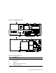
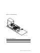
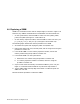
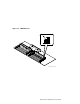
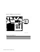
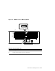
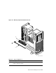

Table 4–6 Cache Size Jumper
Cache Size Jumper J3 Position
128 KB 1–2
64 KB 2–3
No cache installed Either position is okay.
4.7 Replacing the Cache Card
The following steps describe the removal and replacement of the cache card.
Refer to Figure 4–5 and Table 4–7 during the procedure.
1. Use the procedure in Section 4.6 to remove the CPU module.
2. Place the CPU module on an antistatic package, antistatic foam pad, or a
grounded workstation surface.
3. Use a flat-blade screwdriver to lift the cache card and remove it from from
the CPU module. Refer to Figure 4–4 and Table 4–5.
4. Remove the replacement cache card from its antistatic package. Do not
touch any pins.
5. Position the cache card over the CPU module with the guide pin over the
corresponding pin socket.
6. Gently insert the pins on the cache card in the socket on the CPU module.
7. Push the cache card down evenly on the CPU module. Do not bend the
pins.
8. Install the CPU module.
4–12 FRU Removal and Replacement