
User Guide

3 Hardware Installation
1. Turn off the power of the computer system in which the QSCLP-100 is to be
installed.
2. Remove the system cover according to the instructions provided by the
computer manufacturer.
3. Make any desired optional jumper setting changes.
4. Install the QSCLP-100 in any empty PCI expansion slot. The board should be
secured by installing the Option Retaining Bracket (ORB) screw.
5. Replace the system cover according to the instructions provided by the
computer manufacturer.
6. Attach and secure the cable connectors to the desired equipment.
7. Turn on the power of the computer system.
The output of the QSCLP-100 is a 44-pin D-connector. A cable is provided
to convert the D-44 into four standard male D-9 connectors with all control signals
provided to each port (RTS, DTR, CTS, DSR, DCD, and RI).
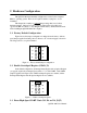
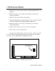
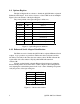
J3
J4
J5
J6
X2
X4
X8
SPAD
Clock multiplier/
scratchpad select
Figure 5 --- Jumper/connector locations
4 QSCLP-100 User's Manual