DSCLP-200/300 Two Channel RS-422/485 Asynchronous Communications Adapter for PCI bus User's Manual QUATECH, INC. 662 Wolf Ledges Parkway Akron, Ohio 44311 TEL: (330) 434-3154 FAX: (330) 434-1409 http://www.quatech.
? 2002 Quatech, Inc. NOTICE The information contained in this document cannot be reproduced in any form without the written consent of Quatech, Inc. Likewise, any software programs that might accompany this document can be used only in accordance with any license agreement(s) between the purchaser and Quatech, Inc. Quatech, Inc. reserves the right to change this documentation or the product to which it refers at any time and without notice.
WARRANTY INFORMATION Quatech, Inc. warrants the DSCLP-200/300 to be free of defects for five (5) years from the date of purchase. Quatech, Inc. will repair or replace any board that fails to perform under normal operating conditions and in accordance with the procedures outlined in this document during the warranty period. Any damage that results from improper installation, operation, or general misuse voids all warranty rights. Please complete the following information and retain for your records.
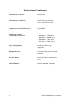
Declaration of Conformity Manufacturer's Name: Quatech Inc.
Table of Contents 1 General Information . . . . . . . . . . . . . . . . . . . . . . . . . . . . . . . . . . . . . . . . . . . . . 1 1.1 Optional Features . . . . . . . . . . . . . . . . . . . . . . . . . . . . . . . . . . . . . . . . . . . . . . . . . 2 1.1.1 "IND" Option --- Surge Suppression Upgrade . . . . . . . . . . . . . . . . . 2 1.1.2 "750" Option --- UART Upgrade . . . . . . . . . . . . . . . . . . . . . . . . . . . . 2 2 Hardware Configuration . . . . . . . . . . . . . . . . . . . . . . . . . . .
1 General Information The Quatech, Inc. DSCLP-200/300(two-port) and SSCLP-200/300 (one-port) provides upto provides two RS-422 or RS-485 asynchronous serial communication interfaces for IBM-compatible personal computer systems using the PCI expansion bus. The DSCLP-200/300 uses Quatech's new Enhanced Serial Adapter design. Legacy serial port data rates are limited to a maximum of 115,200 bits per second. Quatech Enhanced Serial Adapters can achieve data rates as high as 460,800 bits per second.
2 Hardware Configuration The DSCLP-200/300 is automatically configured at boot time by the computer's BIOS or operating system. There are no required switches or jumpers to set for installation. This chapter lists a number of jumper settings that control various hardware features. Jumpers J1-J4, located in a column near the D-9 connectors, control the RS-422 or RS-485 signal line termination.
2.2 Signal Connections The DSCLP-200/300 provides each of two serial ports with four differential signal pairs: TxD, RxD, AUXOUT, and AUXIN. TxD and RxD are always present at the connector. The AUXOUT and AUXIN signals can be used to support RTS/CTS handshaking, external clocking, or external signal loopback. The factory default configuration, as shown in Figure 2, is a loopback of AUXOUT to AUXIN at the connector, with RTS and CTS looped back on the board.
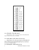
J2 SPAD J4 X4 J5 X2 J10 CTS0_SEL J11 AUX0_SEL0 J12 AUX0_SEL1 J13 RCLK0_SEL J14 TGL0_SEL0 J15 TGL0_SEL1 J16 RXEN0_SEL J17 CTS1_SEL J18 AUX1_SEL0 J19 AUX1_SEL1 J20 RCLK1_SEL J21 TGL1_SEL0 J22 TGL1_SEL1 J23 RXEN1_SEL Right Card Edge Jumpers 2.3.1 CTS0_SEL, CTS1_SEL (J10,17) With NO jumpers on J10 or J17 the mode selection is CTS=AUXIN. With Jumpers installed the mode selection is CTS=RTS. 2.3.
With NO jumpers on J13 or J20 the mode selection is RCLK=TCLK. With Jumpers installed on J13 or J20 the mode selection is RCLK=AUXIN. 2.3.4 TGL0_SEL1,0, TGL1_SEL1,0 (J15,14,22,21) With NO jumpers on J15,14, or J22,21 the mode selection is TXEN=1. With Jumpers installed on J14 or J21 and NO jumpers on J15 or J22, the mode selection is TXEN=DTR. With Jumpers installed on J15 or J22 and NO jumpers on J14 or J21, the mode selection is TXEN=RTS.
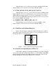
J2 SPAD J4 X4 J5 X2 Figure 4 --- Enable scratchpad registers 2.4.2 Force High-Speed UART Clock (X2 or X4, J4-J5) These jumpers force an increase of the UART input clock frequency by a factor of two, four, or eight. This feature can allow legacy software to use baud rates above 115,200 bits per second. It is also useful if the serial port device driver does not directly support setting the higher baud rates through the Options Register (see page 10).
J2 SPAD J4 X4 J5 X2 X4 mode J2 SPAD J4 X4 J5 X2 X2 mode DSCLP-200/300 User's Manual 7
3 Hardware Installation 1. Turn off the power of the computer system in which the DSCLP-200/300 is to be installed. 2. Remove the system cover according to the instructions provided by the computer manufacturer. 3. Make any desired optional jumper setting changes. 4. Install the DSCLP-200/300 in any empty PCI expansion slot. The board should be secured by installing the Option Retaining Bracket (ORB) screw. 5. Replace the system cover according to the instructions provided by the computer manufacturer. 6.
4 Address Map and Special Registers This chapter explains how the two UARTs and special registers are addressed, as well as the layout of those registers. This material will be of interest to programmers writing driver software for the DSCLP-200/300. 4.1 Base Address and Interrupt Level (IRQ) The base address and IRQ used by the DSCLP-200/300 are determined by the BIOS or operating system. Each serial port uses 8 consecutive I/O locations.
4.2 Enabling the Special Registers The DSCLP-200/300 contains two unique registers, an Interrupt Status Register and an Options Register. These registers are enabled when the SPAD jumper (J13) is removed (factory default). They replace the UART Scratchpad Register on accesses to register address 7. The Interrupt Status Register and Options Register are accessed through the scratchpad location of any UART. The DLAB bit of the UART (Line Control Register, bit 7) is used to select between the two registers.
4.4 Quatech Modem Control Register The Quatech Modem Control Register can be used to setup each port. To access QMCR write a 0xBF to the LCR(base + 3) and a 0x10 to the Opt Reg(base+7). This will allow the user read/write access to QMCR. The QMCR of the entire DSCLP-200/300, as shown in Figure 9a. The individual bits are cleared as the interrupting ports are serviced. The QMCR will need to be written to after the setup by writing a 0x00 to (base+B).
4.5 Options Register The Options Register allows software to identify the DSCLP-200/300 as a Quatech Enhanced Serial Adapter. It also allows software to set the UART clock rate multiplier. Figure 10 shows the structure of the Options Register. The powerup default of the Options Register is all bits zero.
4.5.2 Clock Rate Multiplier A standard serial port operates at a clock speed of 1.8432 MHz. In order to achieve higher data rates, Quatech Enhanced Serial Adapters can operate at two times or four times this standard clock speed. This is controlled by the clock rate multiplier bits in the Options Register. Software can determine the UART clock frequency by reading the clock rate multiplier bits RR1 and RR0 in the Options Register as shown in Figure 12.
5 Windows Configurations 5.1 Windows Millennium 1. After inserting the DSCLP-200/300 for the first time the "Add New Hardware Wizard" will begin. Select "Search for the best driver for your device.". Check the "Removable media" and "Specify location" box. Click the "Next" button. 3. 4. 14 Window will locate the proper INF file and copy the file from the CD. Click the "Next" button. The final dialog screen will verify the file copy from the CD. Click the "Finish" button.
5.2 Windows 2000 1. After inserting a DSCLP-200/300 for the first time, the "Add New Hardware Wizard will appear at start up. Click the "OK" button. 2. The following dialog box insert the Quatech COM CD (shipped with the device). Click the "OK" button. 4. The following dialog box will display the appropriate INF file on the CD in drive. Click the "OK" button. 5. Window will copy the INF file from the CD and display a final dialog indication that the process is complete. Click the "Finish" button.
5.3 Windows 98 1. After inserting a DSCLP-200/300 for the first time, the "Add New Hardware Wizard will appear at start up. Click the "Next" button. 2. Select "Search for the best driver for you device". Click the "Next" button. 3. On the next dialog, select the "CD-ROM DRIVE" check box. Insert the Quatech COM CD (shipped with the device) into the CD-ROM drive. Click the "Next" button.
4. The following dialog box will display the appropriate INF file on the diskette in drive. Click the "Next" button. 5. Window will copy the INF file from the diskette and display a final dialog indication that the process is complete. Click the "Finish" button. Windows 95 maintains a registry of all known hardware installed in your computer. Inside this hardware registry Windows 95 keeps track of all of your system resources, such as I/O locations, IRQ levels, and DMA channels.
2. Select the radio button for "Driver from disk provided by hardware manufacturer." Click the "OK" button to continue. 3. An "Install From Disk" dialog box should pop up. Insert the diskette with the Quatech INF files on it, select the correct drive letter, and click the "OK" button. Windows 95 automatically browses the root directory for an INF file that defines configurations for Multi-function Adapters.
utility. Select Start|Help from within Windows 95 for additional information on this utility. 1. Double click the "System" icon inside the Control Panel folder. This opens up the System Properties box. 2. Click the "Device Manager" tab located along the top of the System Properties box. This lists all hardware devices registered inside the Windows 95 registry. Additional information is available on any of these devices by click on the device name and then selecting the "Properties" button. 3.
Figure 13--- Windows 95 Device Manager 6. The DSCLP-200/300 serial ports are also listed under the group Ports (COM and LPT). Windows 95 does not assign COM1-COM4 to ports addressed at nonstandard locations. The DSCLP-200/300 ports will be enumerated starting with COM5 (or higher) even if lower logical numbers are available. 7. Select any of the Quatech Serial Ports listed under the group Port (COM and LPT) and click the "Properties" button.
Figure 14 --- Windows 95 Device Manager 9. Use the Logical COM Port names to access the serial ports on your DSCLP-200/300 through your software applications. Note: The Logical COM Port name is assigned to your ports by Windows 95.
6 Other Operating Systems Device drivers for Windows NT and OS/2 are also available for the DSCLP-200/300. The board can be used under DOS and other operating systems as well in many circumstances. The software described below can be obtained from the Quatech web site if it did not come with the board. 6.1 Windows NT The Windows NT device driver is installed by running the SETUP program. Up to 256 serial ports are supported.
Quatech's "QTPCI" utility supplies the information required when modifying the serial port settings of the application. This program should be run from real DOS, not in a Windows DOS box. Figure 15 shows the Basic Mode display for the DSCLP-200/300 after the "Q" key has been pressed. In this example, the DSCLP-200/300 uses I/O base address FFA0 hex and IRQ 3. The hardware revision of the DSCLP-200/300 is also displayed.
Figure 16 shows the Expert Mode display for the DSCLP-200/300 after the "Q" key has been pressed. The information from the Basic Mode display is presented along with more details such as the Vendor and Device IDs, PCI Class Code, size of memory and I/O regions, etc. Pressing the "N" key will show similar information for all non-Quatech PCI devices in the system, including those devices integrated on the motherboard. In this example, the "Base addr 0" resource is reserved.
7 External Connections The DSCLP-200/300 provides four differential communication signals per channel. The two output signals are Transmit Data (TxD) and Auxiliary Output (AUXOUT). The two input signals are Receive Data (RxD) and Auxiliary Input (AUXIN). A ground signal is also provided. The available input signals for AUXIN are Clear To Send (CTS) and the Receive Clock (RCLK). The available output signals for AUXOUT are Request To Send (RTS), the Transmit Clock (XCLK), and the AUXIN signal (for loopback).
7.1 RTS/CTS Handshake Transmission of RTS, combined with reception of CTS, allows for hardware handshaking (data flow control) between the UART and the external device. RTS is transmitted on AUXOUT by connecting pins 4 and 5 of the jumper block. CTS is received on AUXIN by connecting pins 1 and 2 of the jumper block. If RTS/CTS handshaking is not desired, the RTS output can be looped back to the CTS input by connecting pins 1 and 4 of the jumper block. Figure 19 shows how to select the RTS/CTS mode.
7.3 XCLK This is the output clock signal used by the transmitter portion of the UART. It is generally connected to the UART's own receive clock input (RCLK). This is done by connecting pins 3 and 6 of the jumper block. If desired, XCLK can be transmitted to an external source over the AUXOUT line by connecting pins 5 and 6 of the jumper block. Figure 21 shows how to select the XCLK mode.
7.5 Half-Duplex/Full-Duplex Selection Using jumper blocks J6 and J8, the transmitters and receivers of each channel can be enabled and disabled by modem control signals. This allows operation in both half-duplex or full-duplex modes. The transmit drivers can be controlled by either the Data Terminal Ready (DTR) or the Request to Send (RTS) output from the UART. If a jumper is applied between pins 1 and 4, the drivers are enabled for TxD and AUXOUT when the UART's DTR signal is asserted.
Jumpers J6, J8 Tx ENABLE 6 3 Rx ENABLE Tx ENABLE 5 2 RTS Tx ENABLE 4 1 DTR Tx ENABLE 6 3 Rx ENABLE Tx ENABLE 5 2 RTS Tx ENABLE 4 1 DTR Tx ENABLE 6 3 Rx ENABLE Tx ENABLE 5 2 RTS Tx ENABLE 4 1 DTR Half-Duplex(DTR) Operation Half-Duplex(RTS) Operation Full-Duplex Operation Figure 23 --- Half- or full-duplex selection AUXOUT RS-422 or RS-485 Driver + - TXEN 6 3 5 2 4 1 XCLK RTS CTS RCLK DTR DSR DCD RI AUXIN RS-422 or RS-485 Receiver + - RXEN 6 3 5 2 4 1 Figure 24 --- O
7.6 Termination Resistors Line termination resistors are provided for the input signals of each of the DSCLP-200/300's RS-422/485 ports. Termination may be selected or removed for individual signal lines using jumper blocks J1-J4.
7.7 RS-422/485 Peripheral Connection The DSCLP-200/300 connects to peripheral equipment through two female D-9 connectors. The serial port connector definitions are listed in Figure 26.
8 PCI Resource Map Listed below are the PCI resources used by the DSCLP-200/300. Such information may be of use to customers writing their own device drivers or other custom software. A detailed description of the DSCLP-200/300's UARTs is available on the Quatech web site. (all numbers in hex) PCI Vendor ID: 0x135C Quatech, Inc.
9 Specifications Bus interface: PCI, 32-bit bus, 5-volt only IBM-compatible computers Dimensions: approx. 5.5" x 3.5" Serial ports Controller: Interface: Transceivers: Differential output: Output rise/fall time: Differential input threshold: Input resistance: Input current: Power requirements +5 volts: 16550 with 16-byte FIFOs (16750 with 64-byte FIFOs optional) Two female D-9 connectors SP491 or compatible 2V min. with 50-ohm load (RS-422) 1.5V min. with 27-ohm load (RS-485) 3ns min., 40ns max.
10 Troubleshooting Listed here are some common problems and frequent causes of those problems. If the information here does not provide a solution, contact Quatech technical support. Any unauthorized repairs or modifications will void the DSCLP-200/300's warranty. Computer will not boot up. 1. Is the DSCLP-200/300 properly inserted? Remove the card and try again. Perhaps try a different expansion slot. 2.
DSCLP-200/300 User's Manual Revision 1.