
User's Manual


GMT100 User Manual
TRACGMT100UM001 -12 -
Figure 5. Typical Digital Input Connection
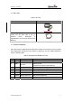
3.8. Analog Input
There is an analog input which is the green wire on GMT100 User Cable, and the analog
input voltage range is from 0 to 32V. The following diagram shows the recommended
connection.
Figure 6. Typical Analog Input Connection
3.9. Digital Output
There is an output which is the brown wire on GMT100 User Cable. This output is used to
drive a siren and the maximum drive current is 750mA. When the siren output is enabled,
the voltage on the siren output is determined by the system power level, if the system
power is 12V, then the siren output voltage is 12V.
Table 7: Electrical Characteristics of Digital Output
Logical State Electrical Characteristics
Active 12V/24V(determined by the system power)
Inactive Floating