
User's Manual

GMT100 User Manual
TRACGMT100UM001 - 9 -
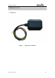
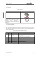
2.2. Parts List
Table 3: Part List
Name Picture
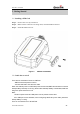
GMT100 Locator
DATA_CABLE_M (Optional)
Please note this data cable is only for
backend server developers or
administrators. It is not in the delivery list of
GMT100
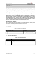
2.3. Interface Definition
There are 8 wires on GMT100 User Cable which contain the connection for power, ignition
input, digital input, analog input, siren output, cut output etc. The user cable’s definition is
shown in following table.
Table 4: Description of GMT100 User Cable
Index Colour Description Comment
1 Red Power External DC power input, 8-32V
2 Black
Ground
System ground
(connect to the vehicle’s frame directly)
3 White Ignition Ignition input, positive trigger
4 Blue Digital input Digital input, negative trigger
5 Green Analog input Analog input, 0-32V
6 Brown Siren output Siren output, high end
7 Yellow Relay output line1 Internal relay output line1.
8 Yellow Relay output line2 Internal relay output line2