GV300 User manual GSM/GPRS/GPS Tracker GV300N User Manual Application Notes: TRACGV300NUM001 Revision: 1.00 TRACGV3SUM001 -1Hhttp://www.queclink.com Hsales@queclink.
GV300N User manual Document Title GV300N User Manual Version 1.00 Date 2014-11-17 Status Release Document Control ID TRACGV300NUM001 General Notes Queclink offers this information as a service to its customers, to support application and engineering efforts that use the products designed by Queclink. The information provided is based upon requirements specifically provided to Queclink by the customers.
GV300N User manual Contents Contents ............................................................................................................................................3 0. Revision History .......................................................................................................................6 1. Introduction...............................................................................................................................7 1.1 Reference ................................
GV300N User manual Table Index TABLE 1. GV300N PROTOCOL REFERENCE.............................................................................8 TABLE 2. TERMS AND ABBREVIATIONS ..................................................................................8 TABLE 3. PARTS LIST..................................................................................................................10 TABLE 4. DESCRIPTION OF 16 PIN CONNECTIONS..............................................................
GV300N User manual Figure Index FIGURE 1. APPEARANCE OF GV300N .........................................................................................9 FIGURE 2. THE 16 PIN CONNECTOR ON THE GV300N........................................................... 11 FIGURE 3. OPEN THE CASE.........................................................................................................13 FIGURE 4. CLOSE THE CASE........................................................................................
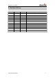
GV300N User manual 0. Revision History Revision Date Author Description of change 1.
GV300N User manual 1. Introduction The GV300N is a powerful GPS locator designed for vehicle or asset tracking. It has superior receiver sensitivity, fast TTFF (Time to First Fix) and supports quad band GSM frequencies GSM850/GSM900/DCS/PCS. Its location can be monitored in real time or periodically tracked by a backend server or other specified terminals. The GV300N has multiple input/output interfaces that can be used for monitoring or controlling external devices.
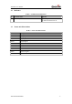
GV300N User manual 1.1 Reference Table 1. GV300N Protocol Reference SN Document name Remark [1] GV300N @Track Air Interface Protocol The air protocol interface between GV300N and backend server. 1.2 Terms and Abbreviations Table 2.
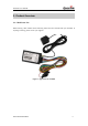
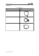
GV300N User manual 2. Product Overview 2.1. Check Parts List Before starting, check whether all the following items have been included with your GV300N. If anything is missing, please contact your supplier. Figure 1.
GV300N User manual 2.2. Parts List Table 3.
GV300N User manual 2.3. Interface Definition The GV300N has a 16 PIN interface connector which contains the connections for power, I/O, RS232, microphone, speaker, etc. The sequence and definition of the 16PIN connector are shown in the following figure: Figure 2. The 16 PIN Connector on the GV300N Table 4. Description of 16 PIN Connections Index Description Comment 1 MICP Single end, 2-2.
GV300N User manual 2.4. GV300N User Cable Color Table 5.
GV300N User manual 3. Get Started 3.1. Open the Case Figure 3. Open the Case Insert the triangular-pry-opener into the gap of the case as shown above, and push the opener up until the case is unsnapped. 3.2. Close the Case Figure 4. Close the Case Place the cover on the bottom in the position as shown in the figure above. Slide the cover against the direction of the arrow until it snaps.
GV300N User manual 3.3. Install a SIM Card Open the case and ensure the unit is not powered (unplug the 16Pin cable and switch the internal battery to the OFF position). Slide the holder right to open the SIM card holder. Insert the SIM card into the holder as shown below with the gold-colored contact area facing down. Take care to align the cut mark. Close the SIM card holder. Close the case. Figure 5. SIM Card Installation 3.4. Install the Internal Backup Battery Figure 6.
GV300N User manual 3.5. Switch on the Backup Battery To use the GV300N backup battery, the switch must be in the ON position. The switch on the case and the ON/OFF position are shown below. Figure 7. Switch and ON/OFF Position Note: 1. The switch must be in the “OFF” position when the GV300N is shipped on an aircraft. 2. When the switch is in the “OFF” position, the battery cannot be charged or discharged. 3.6. Install the External GPS Antenna (Optional) There is a SMA GPS antenna connector on GV300N.
GV300N User manual 3.6.1. GPS Antenna Specification Table 6. GPS Antenna Specification GPS antenna Frequency: 1575.42 MHz Bandwidth >5 MHz Beam width >120 deg Supply voltage 2.7V-3.3V Polarization RHCP Gain Passive: 0 dBi min Active: 15 dB Impedance 50Ω VSWR <2 Noise figure <3 3.7. Power Connection PWR (PIN12)/GND (PIN6) is the power input pin. The input voltage range for this device is from 8V to 32V.
GV300N User manual 3.8. Ignition Detection Table 7. Electrical Characteristics of Ignition Detection Logical status Electrical characteristics Active 5.0V to 32V Inactive 0V to 3V or open Figure 10. Typical Ignition Detection IGN (Pin3) is used for ignition detection. It is strongly recommended to connect this pin to ignition key “RUN” position as shown above.
GV300N User manual Figure 11. 3.10. Typical Digital Input Connection Analog Inputs There are two analog inputs on GV300, and the analog input voltage range is from 0 to 16V. The following diagram shows the recommended connection. Figure 12. Typical Analog Input Connection Note: PIN 15 is a multifunction pin: it can be configured as a digital input or an analog input.
GV300N User manual 3.11. Digital Outputs There are three digital outputs on GV300N. All are of open drain type and the maximum drain current is 150 mA. Each output has the built-in over current PTC resettable fuse. Figure 13. Digital Output Internal Drive Circuit Table 9. Electrical Characteristics of Digital Outputs Logical status Electrical characteristics Enable <1.5V @150 mA Disable Open drain Figure 14.
GV300N User manual Figure 15. Typical Connection with LED Note: 1. OUT1 will latch the output state during reset. 2. Many modern relays come with a flyback diode pre-installed internal to the relay itself. If the relay has this diode, ensure the relay polarity is properly connected. If this diode is not internal, it should be added externally. A common diode such as a 1N4004 will work in most circumstances. 3.12. Device Status LED Figure 16.
GV300N User manual LED Device status LED status GSM (Note 1) Device is searching GSM network. Fast flashing (Note 3) Device has registered to GSM network. Slow flashing (Note 4) SIM card needs pin code to unlock. ON GPS chip is powered off. OFF GPS sends no data or data format error occurs. Slow flashing GPS chip is searching GPS info. Fast flashing GPS chip has gotten GPS info. ON No external power and internal battery voltage is lower than 3.35V.
GV300N User manual Figure 17. Typical Connection with RS232 Port 3.13.1. Connect with Garmin GPS Set GV300N can communicate with Garmin GPS set. The following typical connection is using Queclink AG100 cable. Figure 18. GV300 Connection with Garmin GPS Set Note: Some versions of GV300N can connect with Garmin GPS set by Garmin FMI10/FMI15 cable. Please consult Queclink for detail information.
GV300N User manual 3.13.2. Connect with CAN100 device GV300N can communicate with CAN100 device only by RS232 port. The following picture shows the external interface of CAN100 device. Refer to Figure 19. Figure 19. The External Interface of CAN100 Device The following table 11 shows the definition of CAN100 device’s external interface . Pin No. S1-1 S1-2 S1-3 S1-4 Pin Name TX RX Power Supply Ground Cable Color Blue/Yellow Blue/Red Red Black Table 11.