
Specifications

GV300 @Track Air Interface Protocol
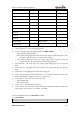
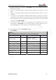
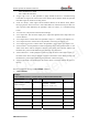
Output Active 1 0|1
Duration <=3 0~255(×100ms) 0
Toggle Times <=3 0~255 0
Sync with FRI 1 0|1 0
Reserved 0
Reserved 0
Reserved 0
Reserved 0
Reserved 0
Reserved 0
Serial Number 4 0000~FFFF
Tail Character 1 $ $
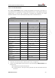
<Analog Input ID 1
~
2>: The analog input port ID.
<Mode>: Working mode of the analog input alarm (+RESP :GTAIS).
z 0: Disable analog input alarm.
z 1: Enable analog input alarm. If the current input voltage is within the range of (<Min
Threshold>, <Max Threshold>), the alarm will be triggered.
z 2: Enable analog input alarm. If the current input voltage is outside the range of
(<Min Threshold>, <Max Threshold>), the alarm will be triggered.
<Min Threshold>: The lower limit to the voltage of the analog input port to trigger the
alarm.
<Max Threshold>: The upper limit to the voltage of the analog input port to trigger the
alarm.
<Sample Rate>: The sampling period of the analog input port.
<Output ID>: Specify the ID of the output port (1 to 3) to output specified wave shape when
the analog input alarm is triggered. If set to 0, no output wave.
<
Output Active>: set the final status of the output port.
z 0: Disable status.
z 1: Enable status.
<
Toggle Times>: The times of the square-wave.
<Sync with FRI>: The device can send the analog input voltage periodically along with fixed
report message. Set this field to 1 to enable it, 0 to disable.
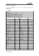
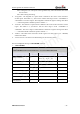
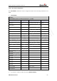
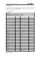
The acknowledgment message of AT+GTAIS command:
¾ +ACK:GTAIS,
Example:
TRACGV300AN002 – 30 –
Queclink
Confidential