
User's Manual


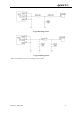

Table Of Contents

2.3.2 RF output power
The module conducted RF output power
Frequency Max Min
GSM850 33dBm ±2dB 5dBm±5dB
EGSM900 33dBm ±2dB 5dBm±5dB
DCS1800 30dBm ±2dB 0dBm±5dB
PCS1900 30dBm ±2dB 0dBm±5dB
2.3.3 RF receiving sensitivity
The module conducted RF receiving sensitivity
Frequency Receive sensitivity
GSM850 < -107dBm
EGSM900 < -107dBm
DCS1800 < -107dBm
PCS1900 < -107dBm
2.3.4 Operating frequencies
The module operating frequencies
Frequency Receive Transmitting channel
GSM850
869 ~ 894MHz 824 ~ 849MHz 128 ~ 251
EGSM900
925 ~ 960MHz 880 ~ 915MHz 0~124, 975~1023
DCS1800
1805 ~ 1880MHz 1710 ~ 1785MHz 512 ~ 885
PCS1900
1930 ~ 1990MHz 1850 ~ 1910MHz 512 ~ 810
2.3.5 Recommended impedance matching circuit
The impedance of M10’s RF_ANT port is 50Ω. If the impedance of antenna is close to 50Ω in all working
frequency bands, the antenna could be connected to the RF_ANT port directly via 50Ω transmission line.
But if the impedance of antenna is not close to 50Ω, a T-type or π-type matching circuit should be inserted
between transmission line and antenna. The matching components should be placed as close as possible to
the antenna’s feed point.
The following 2 figures show the reference designs of T-type and π-type matching circuits.
M10_User_Guide_V1.00 - 8 -