
User's Manual


Wi-Fi&BT Module Series
FC20 Series Hardware Design
FC20_Series_Hardware_Design Confidential / Released 28 / 47
3.9. Antenna Interface
The pin 30 is the RF antenna pad. And the RF interface has an impedance of 50Ω.
3.9.1. Pin Definition of the RF Antenna
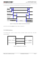
Table 15: Pin Definition of the RF Antenna
Pin Name
Pin No.
I/O
Description
Comment
GND
28
Ground
GND
29
Ground
RF_ANT
30
IO
RF antenna pad
50Ω impedance
GND
31
Ground
3.9.2. Operating Frequency
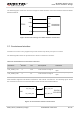
Table 16: Operating Frequency of the Module
Feature
Frequency
Unit
WLAN-2.4GHz
2.412~2.462
GHz
WLAN-5GHz
5.18~5.825
GHz
BT
2.402~2.48
GHz
3.9.3. Reference Design
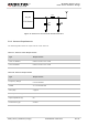
FC20 series module provides an RF antenna pad for antenna connection. The RF trace in host PCB
connected to the module’s RF antenna pad should be microstrip line or other types of RF trace, whose
characteristic impendence should be close to 50Ω. FC20 series module comes with grounding pads
which are next to the antenna pad in order to give a better grounding.
The RF external circuit is recommended as following figure. And a π-type matching circuit should be
reserved for better RF performance. The capacitors are not mounted by default.