EG91 Series Hardware Design LTE Standard Module Series Version: 1.9 Date: 2020-09-03 Status: Preliminary www.quectel.
LTE Standard Module Series EG91 Series Hardware Design Our aim is to provide customers with timely and comprehensive service. For any assistance, please contact our company headquarters: Quectel Wireless Solutions Co., Ltd. Building 5, Shanghai Business Park Phase III (Area B), No.1016 Tianlin Road, Minhang District, Shanghai 200233, China Tel: +86 21 5108 6236 Email: info@quectel.com Or our local office. For more information, please visit: http://www.quectel.com/support/sales.htm.
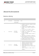
LTE Standard Module Series EG91 Series Hardware Design About the Document Revision History Version 1.0 1.1 1.2 Date Author Description 2017-03-22 Felix YIN/ Yeoman CHEN/ Jackie WANG Initial Felix YIN/ Rex WANG 1. Added band B28A. 2. Updated the description of UMTS and GSM features in Table 2. 3. Updated the functional diagram in Figure 1. 4. Updated module operating frequencies in Table 21. 5. Updated current consumption in Table 26. 6. Updated RF output power in Table 27. 7.
LTE Standard Module Series EG91 Series Hardware Design 8. Updated pin definition of RF antenna in Table 21. 9. Updated module operating frequencies in Table 22. 10. Added description of GNSS antenna interface in Chapter 5.2. 11. Updated antenna requirements in Table 25. 12. Updated RF output power in Table 32. 1.3 1.4 1.5 2019-02-03 2019-03-29 2019-05-24 Ward WANG/ Nathan LIU/ Rex WANG 1. Added new variants EG91-NS, EG91-V, EG91-EC and related contents. 2.
LTE Standard Module Series EG91 Series Hardware Design and Figure 29). 1.7 2019-08-09 Fanny CHEN/ Rex WANG 1. Added ThreadX variant EG91-NAX and updated related contents (Table 1 and 4, Chapter 2.2, 2.3, 3.2 and 5). 2. Added related notes of SPI interface not supported on ThreadX modules (Chapter 3.1, 3.3 and 3.13). 3. Added current consumption of EG91-NAX (Table 37). 4. Updated EG91-NA conducted RF receiving sensitivity (Table 41). 5. Updated EG91-NS conducted RF receiving sensitivity (Table 42). 6.
LTE Standard Module Series EG91 Series Hardware Design Contents About the Document ................................................................................................................................ 2 Contents .................................................................................................................................................... 5 Table Index .............................................................................................................................
LTE Standard Module Series EG91 Series Hardware Design 3.15. 3.16. 3.17. 3.18. STATUS ................................................................................................................................ 53 ADC Interface ....................................................................................................................... 53 Behaviors of RI .....................................................................................................................
LTE Standard Module Series EG91 Series Hardware Design Table Index Table 1: Frequency Bands of EG91 Series Module .......................................................................................... 15 Table 2: Key Features of EG91 series Module .................................................................................................. 16 Table 3: IO Parameters Definition......................................................................................................................
LTE Standard Module Series EG91 Series Hardware Design Table 43: EG91-NA Conducted RF Receiving Sensitivity ................................................................................. 83 Table 44: EG91-NS Conducted RF Receiving Sensitivity ................................................................................. 83 Table 45: EG91-VX Conducted RF Receiving Sensitivity .................................................................................
LTE Standard Module Series EG91 Series Hardware Design Figure Index Figure 1: Functional Diagram .................................................................................................................. 20 Figure 2: Pin Assignment (Top View) ....................................................................................................... 22 Figure 3: Sleep Mode Application via UART............................................................................................
LTE Standard Module Series EG91 Series Hardware Design Figure 42: Module Bottom Dimensions (Top View) .................................................................................. 91 Figure 43: Recommended Footprint (Top View) ...................................................................................... 93 Figure 44: Top View of the Module .......................................................................................................... 94 Figure 45: Bottom View of the Module ........
LTE Standard Module Series EG91 Series Hardware Design 1 Introduction This document defines the EG91 series module and describes its air interface and hardware interface which are connected with customers’ applications. This document can help customers quickly understand module interface specifications, electrical and mechanical details, as well as other related information of EG91 series module.
LTE Standard Module Series EG91 Series Hardware Design ❒ WCDMA II :≤8.000dBi ❒ WCDMA IV :≤5.000dBi ❒ WCDMA V :≤9.416dBi ❒ LTE Band 2 :≤8.000dBi ❒ LTE Band 4:≤5.000dBi ❒ LTE Band 5 :≤9.416dBi ❒ LTE Band 12 :≤8.734dBi ❒ LTE Band 13:≤9.173dBi ❒ LTE Band 25:≤8.000dBi ❒ LTE Band 26:≤9.416dBi 5. This module must not transmit simultaneously with any other antenna or transmitter 6.
LTE Standard Module Series EG91 Series Hardware Design commonly used methods for access to remove the module so that the FCC ID of the module is visible; then an additional permanent label referring to the enclosed module:“Contains Transmitter Module FCC ID: XMR202008EG91NAXD” or “Contains FCC ID: XMR202008EG91NAXD” must be used. The host OEM user manual must also contain clear instructions on how end users can find and/or access the module and the FCC ID.
LTE Standard Module Series EG91 Series Hardware Design 1.2. Safety Information The following safety precautions must be observed during all phases of operation, such as usage, service or repair of any cellular terminal or mobile incorporating EG91 series module. Manufacturers of the cellular terminal should send the following safety information to users and operating personnel, and incorporate these guidelines into all manuals supplied with the product.
LTE Standard Module Series EG91 Series Hardware Design 2 Product Concept 2.1. General Description EG91 series module is an embedded 4G wireless communication module with receive diversity. It supports LTE-FDD/WCDMA/GSM wireless communication, and provides data connectivity on LTE-FDD, DC-HSDPA, HSPA+, HSDPA, HSUPA, WCDMA, EDGE and GPRS networks. It can also provide voice functionality 1) to meet customers’ specific application demands.
LTE Standard Module Series EG91 Series Hardware Design EG91-AUX3) FDD: B1/B2/B3/B4/B5/B7/B8 B28/B66 B1/B2/B5/B8 850/900/1800/ 1900 GPS, GLONASS, BeiDou/Compass, Galileo, QZSS NOTES 1. 2. 3. 1) EG91 contains Telematics version and Data-only version. Telematics version supports voice and data functions, while Data-only version only supports data function. 2) GNSS function is optional. 3) EG91-AUX does not support LTE and WCDMA Rx-diversity. With a compact profile of 29.0mm × 25.0mm × 2.
LTE Standard Module Series EG91 Series Hardware Design LTE Features Support up to non-CA Cat 1 FDD Support 1.4/3/5/10/15/20MHz RF bandwidth Support MIMO in DL direction LTE-FDD: Max 10Mbps (DL), Max 5Mbps (UL) UMTS Features Support 3GPP R8 DC-HSDPA, HSPA+, HSDPA, HSUPA and WCDMA Support QPSK, 16-QAM and 64-QAM modulation DC-HSDPA: Max 42Mbps (DL) HSUPA: Max 5.76Mbps (UL) WCDMA: Max 384Kbps (DL), Max 384Kbps (UL) R99: CSD: 9.
LTE Standard Module Series EG91 Series Hardware Design USB Interface UART Interface Compliant with USB 2.0 specification (slave only); the data transfer rate can reach up to 480Mbps Used for AT command communication, data transmission, GNSS NMEA sentences output, software debugging, firmware upgrade and voice over USB Support USB serial drivers for: Windows 7/8/8.1/10, Linux 2.6~5.4, Android 4.x/5.x/6.x/7.x/8.x/9.x, etc.
LTE Standard Module Series EG91 Series Hardware Design 3. 4. 3) Within extended temperature range, the module remains the ability to establish and maintain a voice, SMS, data transmission, emergency call*, etc. There is no unrecoverable malfunction. There are also no effects on radio spectrum and no harm to radio network. Only one or more parameters like Pout might reduce in their value and exceed the specified tolerances.
LTE Standard Module Series EG91 Series Hardware Design Figure 1: Functional Diagram NOTE 1) GNSS antenna interface is only supported on EG91-NA/-NS/-VX/-EX/-NAX/-NAXD/-AUX. 2.4. Evaluation Board Quectel provides a complete set of evaluation tools to facilitate the use and testing of EG91 series module. The evaluation tool kit includes the evaluation board (UMTS<E EVB), USB data cable, earphone, antenna and other peripherals. For more details, please refer to document [7].
LTE Standard Module Series EG91 Series Hardware Design 3 Application Interfaces 3.1. General Description EG91 series module is equipped with 62-pin 1.1mm pitch SMT pads and 44-pin ground/reserved pads that can be connected to customers’ cellular application platforms.
LTE Standard Module Series EG91 Series Hardware Design 3.2. Pin Assignment The following figure shows the pin assignment of EG91 series module.
LTE Standard Module Series EG91 Series Hardware Design NOTES 1. 2. 3. 4. 1) PWRKEY output voltage is 0.8V because of the diode drop in the Qualcomm chipset. Keep all RESERVED pins and unused pins unconnected. GND pads should be connected to ground in the design. Please note that the definition of pin 49 and 56 are different among EG91-NA/-NS/-VX/-EX/-NAX/-NAXD/-AUX and EG91-E. For more details, please refer to Table 4. 3.3.
LTE Standard Module Series EG91 Series Hardware Design VBAT_RF 52, 53 VDD_EXT 29 GND 3, 31, 48, 50, 54, 55, 58, 59, 61, 62, 67~74, 79~82, 89~91, 100~106 PI PO Power supply for module’s RF part Provide 1.8V for external circuit Vmax=4.3V Vmin=3.3V Vnorm=3.8V It must be provided with sufficient current up to 1.8A in a burst transmission. Vnorm=1.8V IOmax=50mA Power supply for external GPIO’s pull up circuits. If unused, keep it open.
LTE Standard Module Series EG91 Series Hardware Design Vnorm=5.0V open. USB_DP 9 IO USB differential data bus (+) USB 2.0 compliant Require differential impedance of 90Ω. USB_DM 10 IO USB differential data bus (-) USB 2.0 compliant Require differential impedance of 90Ω. I/O Description DC Characteristics Comment (U)SIM Interfaces Pin Name USIM_GND Pin No. Connect to ground of (U)SIM card connector.
LTE Standard Module Series EG91 Series Hardware Design USIM1_RST USIM1_ PRESENCE 44 42 DO DI Reset signal of (U)SIM card (U)SIM card insertion detection For 1.8V (U)SIM: VOLmax=0.45V VOHmin=1.35V For 3.0V (U)SIM: VOLmax=0.45V VOHmin=2.55V VILmin=-0.3V VILmax=0.6V VIHmin=1.2V VIHmax=2.0V For 1.8V (U)SIM: Vmax=1.9V Vmin=1.
LTE Standard Module Series EG91 Series Hardware Design USIM2_ PRESENCE 83 DI (U)SIM card insertion detection VILmin=-0.3V VILmax=0.6V VIHmin=1.2V VIHmax=2.0V I/O Description DC Characteristics Comment DO Ring indicator VOLmax=0.45V VOHmin=1.35V 1.8V power domain. If unused, keep it open. DO Data carrier detection VOLmax=0.45V VOHmin=1.35V 1.8V power domain. If unused, keep it open. Clear to send VOLmax=0.45V VOHmin=1.35V 1.8V power domain. If unused, keep it open.
LTE Standard Module Series EG91 Series Hardware Design VIHmin=1.2V VIHmax=2.0V open. Description DC Characteristics Comment PCM data input VILmin=-0.3V VILmax=0.6V VIHmin=1.2V VIHmax=2.0V 1.8V power domain. If unused, keep it open. PCM data output VOLmax=0.45V VOHmin=1.35V 1.8V power domain. If unused, keep it open. PCM data frame synchronization signal VOLmax=0.45V VOHmin=1.35V VILmin=-0.3V VILmax=0.6V VIHmin=1.2V VIHmax=2.0V 1.8V power domain. In master mode, it is an output signal.
LTE Standard Module Series EG91 Series Hardware Design 24 AI General-purpose analog to digital converter Pin No. I/O Description DC Characteristics Comment DO Clock signal of SPI interface VOLmax=0.45V VOHmin=1.35V 1.8V power domain. If unused, keep it open. DO Master output slave input of SPI interface VOLmax=0.45V VOHmin=1.35V 1.8V power domain. If unused, keep it open. 28 DI Master input slave output of SPI interface VILmin=-0.3V VILmax=0.6V VIHmin=1.2V VIHmax=2.0V 1.8V power domain.
LTE Standard Module Series EG91 Series Hardware Design processor sleep state detection USB_BOOT 75 VILmax=0.6V VIHmin=1.2V VIHmax=2.0V If unused, keep it open. DI Force the module to enter emergency download mode VILmin=-0.3V VILmax=0.6V VIHmin=1.2V VIHmax=2.0V 1.8V power domain. It is recommended to reserve the test points. I/O Description DC Characteristics Comment RESERVED Pins Pin Name NC RESERVED Pin No.
LTE Standard Module Series EG91 Series Hardware Design Airplane Mode AT+CFUN command or W_DISABLE# pin can set the module to enter airplane mode. In this case, RF function will be invalid. Sleep Mode In this mode, the current consumption of the module will be reduced to the minimal level. During this mode, the module can still receive paging message, SMS, voice call and TCP/UDP data from the network normally. Power Down Mode In this mode, the power management unit shuts down the power supply.
LTE Standard Module Series EG91 Series Hardware Design AP_READY will detect the sleep state of host (can be configured to high level or low level detection). Please refer to AT+QCFG="apready" for details. 3.5.1.2. USB Application with USB Remote Wakeup Function If the host supports USB suspend/resume and remote wakeup functions, the following three preconditions must be met to let the module enter sleep mode. Execute AT+QSCLK=1 command to enable sleep mode.
LTE Standard Module Series EG91 Series Hardware Design Figure 5: Sleep Mode Application with RI Sending data to EG91 series module through USB will wake up the module. When module has a URC to report, RI signal will wake up the host. 3.5.1.4. USB Application without USB Suspend Function If the host does not support USB suspend function, USB_VBUS should be disconnected with an external control circuit to let the module enter sleep mode. Execute AT+QSCLK=1 command to enable sleep mode.
LTE Standard Module Series EG91 Series Hardware Design NOTE Please pay attention to the level match shown in dotted line between the module and the host. Please refer to document [1] for more details about EG91 series module power management application. 3.5.2. Airplane Mode When the module enters airplane mode, the RF function will be disabled, and all AT commands related to it will be inaccessible. This mode can be set via the following ways. Hardware: The W_DISABLE# pin is pulled up by default.
LTE Standard Module Series EG91 Series Hardware Design Table 6: Pin Definition of VBAT and GND Pin Name Pin No. Description Min. Typ. Max. Unit VBAT_RF 52, 53 Power supply for module’s RF part. 3.3 3.8 4.3 V VBAT_BB 32, 33 Power supply for module’s baseband part. 3.3 3.8 4.3 V GND 3, 31, 48, 50, 54, 55, 58, 59, 61, 62, 67~74, 79~82, 89~91, 100~106 Ground - 0 - V 3.6.2. Decrease Voltage Drop The power supply range of the module is from 3.3V to 4.3V.
LTE Standard Module Series EG91 Series Hardware Design VBAT VBAT_RF VBAT_BB + + D1 C1 WS4.5D3HV 100uF C2 100nF C3 C4 33pF 10pF C5 100uF C6 C7 C8 100nF 33pF 10pF Module Figure 8: Star Structure of Power Supply 3.6.3. Reference Design for Power Supply Power design for the module is very important, as the performance of the module largely depends on the power source. The power supply should be able to provide sufficient current up to 2A at least.
LTE Standard Module Series EG91 Series Hardware Design 3.7. Power-on/off Scenarios 3.7.1. Turn on Module Using the PWRKEY The following table shows the pin definition of PWRKEY. Table 7: Pin Definition of PWRKEY Pin Name PWRKEY Pin No. 15 Description Turn on/off the module DC Characteristics Comment VOH=0.8V The output voltage is 0.8V because of the diode drop in the Qualcomm chipset.
LTE Standard Module Series EG91 Series Hardware Design Figure 11: Turn on the Module Using Button The power-on scenario is illustrated in the following figure. NOTE 1 VBAT ≥500ms V H =0.8V PWRKEY VIL≤0.5V About 100ms VDD_EXT ≥100ms. After this time, the BOOT_CONFIG pins can be set to high level by external circuit.
LTE Standard Module Series EG91 Series Hardware Design NOTES 1. 2. Please make sure that VBAT is stable before pulling down PWRKEY pin. The time between them is no less than 30ms. PWRKEY can be pulled down directly to GND with a recommended 10KΩ resistor if module needs to be powered on automatically and shutdown is not needed. 3.7.2. Turn off Module Either of the following methods can be used to turn off the module: Use the PWRKEY pin. Use AT+QPOWD command. 3.7.2.1.
LTE Standard Module Series EG91 Series Hardware Design NOTES 1. 2. In order to avoid damaging internal flash, please do not switch off the power supply when the module works normally. Only after the module is shut down by PWRKEY or AT command, the power supply can be cut off. When turning off module with the AT command, please keep PWRKEY at high level after the execution of the command. Otherwise, the module will be turned on again after being shut down. 3.8.
LTE Standard Module Series EG91 Series Hardware Design Figure 15: Reference Circuit of RESET_N by Using Button The reset scenario is illustrated in the following figure. Figure 16: Timing of Resetting Module NOTES 1. 2. Use RESET_N only when turning off the module by AT+QPOWD command and PWRKEY pin failed. Ensure that there is no large capacitance on PWRKEY and RESET_N pins. 3.9. (U)SIM Interfaces EG91 series module provides two (U)SIM interfaces, and only one (U)SIM card can work at a time.
LTE Standard Module Series EG91 Series Hardware Design Table 9: Pin Definition of (U)SIM Interfaces Pin Name Pin No. I/O Description Comment Either 1.8V or 3.0V is supported by the module automatically.
LTE Standard Module Series EG91 Series Hardware Design Figure 17: Reference Circuit of (U)SIM Interface with an 8-pin (U)SIM Card Connector If (U)SIM card detection function is not needed, please keep USIM_PRESENCE unconnected. A reference circuit of (U)SIM interface with a 6-pin (U)SIM card connector is illustrated in the following figure.
LTE Standard Module Series EG91 Series Hardware Design Make sure the bypass capacitor between USIM_VDD and USIM_GND less than 1uF, and place it as close to (U)SIM card connector as possible. If the ground is complete on customers’ PCB, USIM_GND can be connected to PCB ground directly. To avoid cross-talk between USIM_DATA and USIM_CLK, keep them away from each other and shield them with surrounded ground.
LTE Standard Module Series EG91 Series Hardware Design Figure 19: Reference Circuit of USB Interface A common mode choke L1 is recommended to be added in series between the module and customer’s MCU in order to suppress EMI spurious transmission. Meanwhile, the 0Ω resistors (R3 and R4) should be added in series between the module and the test points so as to facilitate debugging, and the resistors are not mounted by default.
LTE Standard Module Series EG91 Series Hardware Design The main UART interface supports 9600bps, 19200bps, 38400bps, 57600bps, 115200bps, 230400bps, 460800bps, 921600bps and 3000000bps baud rates, and the default is 115200bps. It supports RTS and CTS hardware flow control, and is used for AT command communication only. The debug UART interface supports 115200bps baud rate. It is used for Linux console and log output. The following tables show the pin definition of the two UART interfaces.
LTE Standard Module Series EG91 Series Hardware Design VOL 0 0.45 V VOH 1.35 1.8 V The module provides 1.8V UART interfaces. A level translator should be used if customers’ application is equipped with a 3.3V UART interface. A level translator TXS0108EPWR provided by Texas Instruments is recommended. The following figure shows a reference design. Figure 20: Reference Circuit with Translator Chip Please visit http://www.ti.com for more information.
LTE Standard Module Series EG91 Series Hardware Design Figure 21: Reference Circuit with Transistor Circuit NOTE Transistor circuit solution is not suitable for applications with high baud rates exceeding 460Kbps. 3.12.
LTE Standard Module Series EG91 Series Hardware Design Figure 22: Primary Mode Timing Figure 23: Auxiliary Mode Timing The following table shows the pin definition of PCM and I2C interfaces which can be applied on audio codec design.
LTE Standard Module Series EG91 Series Hardware Design Table 14: Pin Definition of PCM and I2C Interfaces Pin Name Pin No. I/O Description Comment PCM_DIN 6 DI PCM data input 1.8V power domain PCM_DOUT 7 DO PCM data output 1.8V power domain PCM_SYNC 5 IO PCM data frame synchronization signal 1.8V power domain PCM_CLK 4 IO PCM data bit clock 1.8V power domain I2C_SCL 40 OD I2C serial clock Require an external pull-up to 1.
LTE Standard Module Series EG91 Series Hardware Design 3.13. SPI Interface SPI interface of EG91 series module acts as the master only. It provides a duplex, synchronous and serial communication link with the peripheral devices. It is dedicated to one-to-one connection, without chip selection. Its operation voltage is 1.8V with clock rates up to 50MHz. The following table shows the pin definition of SPI interface. Table 15: Pin Definition of SPI Interface Pin Name Pin No.
LTE Standard Module Series EG91 Series Hardware Design 3.14. Network Status Indication The module provides one network indication pin: NETLIGHT. The pin is used to drive a network status indication LED. The following tables describe the pin definition and logic level changes of NETLIGHT in different network status. Table 16: Pin Definition of Network Status Indicator Pin Name Pin No. I/O Description Comment NETLIGHT 21 DO Indicate the module’s network activity status 1.
LTE Standard Module Series EG91 Series Hardware Design 3.15. STATUS The STATUS pin is set as the module’s operation status indicator. It will output high level when the module is powered on. The following table describes the pin definition of STATUS. Table 18: Pin Definition of STATUS Pin Name Pin No. I/O Description Comment STATUS 20 DO Indicate the module’s operation status 1.8V power domain. If unused, keep it open. The following figure shows the reference circuit of STATUS.
LTE Standard Module Series EG91 Series Hardware Design Table 19: Pin Definition of ADC Interface Pin Name Pin No. I/O Description Comment ADC0 24 AI General-purpose analog to digital converter If unused, keep this pin open. The following table describes the characteristics of ADC interface. Table 20: Characteristics of ADC Interface Parameter Min. ADC0 Voltage Range 0.3 Typ. ADC Resolution Max. Unit VBAT_BB V 15 bits NOTES 1. 2.
LTE Standard Module Series EG91 Series Hardware Design Table 21: Default Behaviors of RI State Response Idle RI keeps at high level URC RI outputs 120ms low pulse when a new URC returns 3.18. USB_BOOT Interface EG91 series module provides a USB_BOOT pin. Customers can pull up USB_BOOT to 1.8V before VDD_EXT is powered up, and the module will enter emergency download mode when it is powered on. In this mode, the module supports firmware upgrade over USB interface.
LTE Standard Module Series EG91 Series Hardware Design NOTE 1 VBAT ≥500ms VH=0.8V PWRKEY VIL≤0.5V About 100ms VDD_EXT USB_BOOT can be pul led up to 1.8V before VDD_EXT Is powered up, and the module will enter emerge ncy download mode wh en i t is powered on. USB_BOOT RESET_N Figure 29: Timing Sequence for Entering Emergency Download Mode NOTES 1. 2. Please make sure that VBAT is stable before pulling down PWRKEY pin.
LTE Standard Module Series EG91 Series Hardware Design 4 GNSS Receiver 4.1. General Description EG91 series module includes a fully integrated global navigation satellite system solution that supports Gen8C-Lite of Qualcomm (GPS, GLONASS, BeiDou, Galileo and QZSS). EG91 series module supports standard NMEA-0183 protocol, and outputs NMEA sentences at 1Hz data update rate via USB interface by default. By default, EG91 series module GNSS engine is switched off. It has to be switched on via AT command.
LTE Standard Module Series EG91 Series Hardware Design Hot start @open sky Accuracy (GNSS) CEP-50 Autonomous 1.8 s XTRA enabled 3.4 s Autonomous @open sky <2.5 m NOTES 1. 2. 3. Tracking sensitivity: the minimum GNSS signal power at which the module can maintain lock (keep positioning for at least 3 minutes continuously). Reacquisition sensitivity: the minimum GNSS signal power required for the module to maintain lock within 3 minutes after loss of lock.
LTE Standard Module Series EG91 Series Hardware Design 5 Antenna Interfaces EG91 series module antenna interfaces include a main antenna interface and an Rx-diversity antenna interface which is used to resist the fall of signals caused by high speed movement and multipath effect, and a GNSS antenna interface which is only supported on EG91-NA/-NS/-VX/-EX/-NAX/-NAXD/-AUX. The impedance of the antenna port is 50Ω. 5.1. Main/Rx-diversity Antenna Interfaces 5.1.1.
LTE Standard Module Series EG91 Series Hardware Design PCS1900 1850~1910 1930~1990 MHz WCDMA B1 1920~1980 2110~2170 MHz WCDMA B2 1850~1910 1930~1990 MHz WCDMA B4 1710~1755 2110~2155 MHz WCDMA B5 824~849 869~894 MHz WCDMA B8 880~915 925~960 MHz LTE-FDD B1 1920~1980 2110~2170 MHz LTE FDD B2 1850~1910 1930~1990 MHz LTE-FDD B3 1710~1785 1805~1880 MHz LTE FDD B4 1710~1755 2110~2155 MHz LTE FDD B5 824~849 869~894 MHz LTE-FDD B7 2500~2570 2620~2690 MHz LTE-FDD B8 8
LTE Standard Module Series EG91 Series Hardware Design Figure 30: Reference Circuit of RF Antenna Interface NOTES 1. Keep a proper distance between the main antenna and the Rx-diversity antenna to improve the receiving sensitivity. 2. ANT_DIV function is enabled by default. AT+QCFG="divctl",0 command can be used to disable receive diversity. Place the π-type matching components (R1/C1/C2, R2/C3/C4) as close to the antenna as possible. 3. 5.1.4.
LTE Standard Module Series EG91 Series Hardware Design Figure 32: Coplanar Waveguide Design on a 2-layer PCB Figure 33: Coplanar Waveguide Design on a 4-layer PCB (Layer 3 as Reference Ground) Figure 34: Coplanar Waveguide Design on a 4-layer PCB (Layer 4 as Reference Ground) EG91_Series_Hardware_Design 62 / 106
LTE Standard Module Series EG91 Series Hardware Design In order to ensure RF performance and reliability, the following principles should be complied with in RF layout design: Use an impedance simulation tool to accurately control the characteristic impedance of RF traces to 50 Ω. The GND pins adjacent to RF pins should not be designed as thermal relief pads, and should be fully connected to ground.
LTE Standard Module Series EG91 Series Hardware Design QZSS 1575.42 MHz A reference design of GNSS antenna is shown as below. Figure 35: Reference Circuit of GNSS Antenna NOTES 1. 2. An external LDO can be selected to supply power according to the active antenna requirement. If the module is designed with a passive antenna, then the VDD circuit is not needed. 5.3. Antenna Installation 5.3.1.
LTE Standard Module Series EG91 Series Hardware Design GSM/WCDMA/LTE VSWR: ≤ 2 Efficiency : > 30% Max input power: 50W Input impedance: 50Ω Cable insertion loss: < 1dB (GSM850,EGSM900, WCDMA B5/B8, LTE-FDD B5/B8/B12/B13/B20/B26/B28) Cable insertion loss: < 1.
LTE Standard Module Series EG91 Series Hardware Design U.FL-LP serial connectors listed in the following figure can be used to match the U.FL-R-SMT. Figure 37: Mechanicals of U.FL-LP Connectors The following figure describes the space factor of mated connector. Figure 38: Space Factor of Mated Connector (Unit: mm) For more details, please visit http://www.hirose.com.
LTE Standard Module Series EG91 Series Hardware Design 6 Electrical, Reliability and Radio Characteristics 6.1. Absolute Maximum Ratings Absolute maximum ratings for power supply and voltage on digital and analog pins of the module are listed in the following table. Table 29: Absolute Maximum Ratings Parameter Min. Max. Unit VBAT_RF/VBAT_BB -0.3 4.7 V USB_VBUS -0.3 5.5 V Peak Current of VBAT_BB 0 0.8 A Peak Current of VBAT_RF 0 1.8 A Voltage at Digital Pins -0.3 2.
LTE Standard Module Series EG91 Series Hardware Design Voltage drop during burst transmission Maximum power control level on EGSM900 IVBAT Peak supply current (during transmission slot) Maximum power control level on EGSM900 USB_VBUS USB connection detection 3.0 400 mV 1.8 2.0 A 5.0 5.25 V 6.3. Operation and Storage Temperatures The operation and storage temperatures are listed in the following table. Table 31: Operation and Storage Temperatures Parameter Min. Typ. Max.
LTE Standard Module Series EG91 Series Hardware Design 6.4. Current Consumption The values of current consumption are shown below. Table 32: EG91-E Current Consumption Parameter Description Conditions Typ. Unit OFF state Power down 13 μA AT+CFUN=0 (USB disconnected) 1.1 mA GSM DRX=2 (USB disconnected) 2.0 mA GSM DRX=5 (USB suspended) 1.9 mA GSM DRX=9 (USB disconnected) 1.3 mA WCDMA PF=64 (USB disconnected) 1.7 mA WCDMA PF=64 (USB suspended) 2.
LTE Standard Module Series EG91 Series Hardware Design EDGE data transfer WCDMA data transfer EGSM900 1DL/4UL @29.26dBm 619 mA DCS1800 4DL/1UL @29.2dBm 165 mA DCS1800 3DL/2UL @29.13dBm 267 mA DCS1800 2DL/3UL @29.01dBm 406 mA DCS1800 1DL/4UL @28.86dBm 467 mA EGSM900 4DL/1UL PCL=8 @27.1dBm 163 mA EGSM900 3DL/2UL PCL=8 @27.16dBm 274 mA EGSM900 2DL/3UL PCL=8 @26.91dBm 383 mA EGSM900 1DL/4UL PCL=8 @26.12dBm 463 mA DCS1800 4DL/1UL PCL=2 @25.54dBm 136 mA DCS1800 3DL/2UL PCL=2 @25.
LTE Standard Module Series EG91 Series Hardware Design WCDMA voice call WCDMA B1 CH10700 @23.06dBm 555 mA WCDMA B8 CH3012 @23.45dBm 535 mA Table 33: EG91-NA Current Consumption Parameter Description Conditions Typ. Unit OFF state Power down 13 μA AT+CFUN=0 (USB disconnected) 1.0 mA WCDMA PF=64 (USB disconnected) 2.2 mA WCDMA PF=64 (USB suspended) 2.5 mA WCDMA PF=512 (USB disconnected) 1.4 mA LTE-FDD PF=64 (USB disconnected) 2.6 mA LTE-FDD PF=64 (USB suspended) 2.
LTE Standard Module Series EG91 Series Hardware Design WCDMA voice call LTE-FDD B5 CH2525 @23.39dBm 601 mA LTE-FDD B12 CH5060 @23.16dBm 650 mA LTE-FDD B13 CH5230 @23.36dBm 602 mA WCDMA B2 CH9938 @23.34dBm 627 mA WCDMA B4 CH1537 @23.47dBm 591 mA WCDMA B5 CH4357 @ 23.37dBm 536 mA Table 34: EG91-NS Current Consumption Parameter Description Conditions Typ. Unit OFF state Power down 8 μA AT+CFUN=0 (USB disconnected) 1.
LTE Standard Module Series EG91 Series Hardware Design LTE data transfer WCDMA voice call WCDMA B5 HSDPA CH4407 @23.05dBm 553 mA WCDMA B5 HSUPA CH4407 @ 22.91dBm 556 mA LTE-FDD B2 CH1100 @23.26dBm 724 mA LTE-FDD B4 CH2175 @23.52dBm 693 mA LTE-FDD B5 CH2525 @23.51dBm 613 mA LTE-FDD B12 CH5060 @23.39dBm 634 mA LTE-FDD B13 CH5230 @23.3dBm 672 mA LTE-FDD B25 CH8590@ 23.64dBm 739 mA LTE-FDD B26 CH8765@ 23.34dBm 647 mA WCDMA B2 CH9938 @23.39dBm 571 mA WCDMA B4 CH1738 @23.
LTE Standard Module Series EG91 Series Hardware Design Table 36: EG91-EX Current Consumption Parameter Description Conditions Typ. Unit OFF state Power down 15 μA AT+CFUN=0 (USB disconnected) 1.3 mA GSM DRX=2 (USB disconnected) 2.3 mA GSM DRX=5 (USB suspend) 2.0 mA GSM DRX=9 (USB disconnected) 1.6 mA WCDMA PF=64 (USB disconnected) 1.8 mA WCDMA PF=64 (USB suspend) 2.1 mA WCDMA PF=512 (USB disconnected) 1.3 mA LTE-FDD PF=64 (USB disconnected) 2.
LTE Standard Module Series EG91 Series Hardware Design EDGE data transfer WCDMA data transfer LTE data transfer GSM voice call WCDMA voice call DCS1800 2DL/3UL @29.21dBm 355.4 mA DCS1800 1DL/4UL @29.07dBm 455.7 mA EGSM900 4DL/1UL PCL=8 @27.29dBm 169.5 mA EGSM900 3DL/2UL PCL=8 @27.01dBm 305.06 mA EGSM900 2DL/3UL PCL=8 @26.86dBm 434 mA EGSM900 1DL/4UL PCL=8 @25.95dBm 548 mA DCS1800 4DL/1UL PCL=2 @26.11dBm 135 mA DCS1800 3DL/2UL PCL=2 @25.8dBm 244 mA DCS1800 2DL/3UL PCL=2 @25.
LTE Standard Module Series EG91 Series Hardware Design Table 37: EG91-NAX Current Consumption Parameter Description Conditions Typ. Unit OFF state Power down 9 μA AT+CFUN=0 (USB disconnected) 1.1 mA WCDMA PF=64 (USB disconnected) 2.1 mA WCDMA PF=64 (USB suspend) 2.2 mA WCDMA PF=512 (USB disconnected) 1.6 mA LTE-FDD PF=64 (USB disconnected) 2.6 mA LTE-FDD PF=64 (USB suspend) 2.7 mA LTE-FDD PF=256 (USB disconnected) 1.8 mA WCDMA PF=64 (USB disconnected) 16.
LTE Standard Module Series EG91 Series Hardware Design WCDMA voice call LTE-FDD B25 @22.96dBm 689 mA LTE-FDD B26 @23.11dBm 636 mA WCDMA B2 @23.08dBm 581 mA WCDMA B4 @23.21dBm 557 mA WCDMA B5 @23.29dBm 534 mA Table 38: EG91-NAXD Current Consumption Parameter Description Conditions Typ. Unit OFF state Power down 9 μA AT+CFUN=0 (USB disconnected) 1.1 mA WCDMA PF=64 (USB disconnected) 2.1 mA WCDMA PF=64 (USB suspend) 2.2 mA WCDMA PF=512 (USB disconnected) 1.
LTE Standard Module Series EG91 Series Hardware Design LTE data transfer WCDMA B5 HSUPA @22.31dBm 523 mA LTE-FDD B2 @23.08dBm 694 mA LTE-FDD B4 @23.31dBm 691 mA LTE-FDD B5 @23.23dBm 586 mA LTE-FDD B12 @23.03dBm 613 mA LTE-FDD B13 @23.13dBm 626 mA LTE-FDD B25 @22.96dBm 689 mA LTE-FDD B26 @23.11dBm 636 mA Table 39: EG91-AUX Current Consumption Parameter Description Conditions Typ. Unit OFF state Power down 10 μA AT+CFUN=0 (USB disconnected) 1.
LTE Standard Module Series EG91 Series Hardware Design GPRS data transfer EDGE data transfer WCDMA PF = 64 (USB connected) 28 mA LTE-FDD PF = 64 (USB disconnected) 18 mA LTE-FDD PF = 64 (USB connected) 29 mA GSM850 4DL/1UL @ 32.48 dBm 217.9 mA GSM850 3DL/2UL @ 31.89dBm 372.3 mA GSM850 2DL/3UL @ 29.45 dBm 432.9 mA GSM850 1DL/4UL @ 28.31 dBm 513.9 mA EGSM900 4DL/1UL @ 33.17 dBm 235.1 mA EGSM900 3DL/2UL @ 32.16 dBm 387.7 mA EGSM900 2DL/3UL @ 29.77 dBm 446.
LTE Standard Module Series EG91 Series Hardware Design WCDMA data transfer LTE data transfer EGSM900 2DL/3UL PCL = 8 @ 23.62 dBm 411.4 mA EGSM900 1DL/4UL PCL = 8 @ 22.27 dBm 520.8 mA DCS1800 4DL/1UL PCL = 2 @ 26.12 dBm 139.4 mA DCS1800 3DL/2UL PCL = 2 @ 25.02 dBm 250.7 mA DCS1800 2DL/3UL PCL = 2 @ 22.75 dBm 355.3 mA DCS1800 1DL/4UL PCL = 2 @ 21.47 dBm 452.1 mA PCS1900 4DL/1UL PCL = 2 @ 26.36 dBm 138.3 mA PCS1900 3DL/2UL PCL = 2 @ 25.2 dBm 248.2 mA PCS1900 2DL/3UL PCL = 2 @ 22.
LTE Standard Module Series EG91 Series Hardware Design GSM voice call WCDMA voice call LTE-FDD B28 @ 22.84 dBm 670.0 mA LTE-FDD B66 @ 22.73 dBm 725.9 mA GSM850 PCL5 @32.57dBm 227.8 mA EGSM900 PCL5 @33.21dBm 253.8 mA DCS1800 PCL0 @30.24dBm 168.0 mA PCS1900 PCL0 @30.33dBm 166.8 mA WCDMA B1 @22.93dBm 656.2 mA WCDMA B2 @22.95dBm 579.8 mA WCDMA B5 @22.54dBm 589.8 mA WCDMA B8 @22.47dBm 627.8 mA Conditions Typ.
LTE Standard Module Series EG91 Series Hardware Design EGSM900 33dBm±2dB 5dBm±5dB DCS1800 30dBm±2dB 0dBm±5dB PCS1900 30dBm±2dB 0dBm±5dB GSM850 (8-PSK) 27dBm±3dB 5dBm±5dB EGSM900 (8-PSK) 27dBm±3dB 5dBm±5dB DCS1800 (8-PSK) 26dBm±3dB 0dBm±5dB PCS1900 (8-PSK) 26dBm±3dB 0dBm±5dB WCDMA B1/B2/B4/B5/B8 24dBm+1/-3dB < -49dBm LTE-FDD B1/B2/B3/B4/B5/B7/ B8/B12/B13/B20/B25/B26/B28/B66 23dBm±2dB < -39dBm NOTE In GPRS 4 slots TX mode, the maximum output power is reduced by 3.0dB.
LTE Standard Module Series EG91 Series Hardware Design LTE-FDD B3 (10MHz) -98.3dBm -98.5dBm -101.5dBm -93.3dBm LTE-FDD B7 (10MHz) -96.3dBm -98.4dBm -101.3dBm -94.3dBm LTE-FDD B8 (10MHz) -97.1dBm -99.1dBm -101.2dBm -93.3dBm LTE-FDD B20 (10MHz) -97dBm -99dBm -101.3dBm -93.3dBm LTE-FDD B28A (10MHz) -98.3dBm -99dBm -101.4dBm -94.8dBm Table 43: EG91-NA Conducted RF Receiving Sensitivity Receiving Sensitivity (Typ.
LTE Standard Module Series EG91 Series Hardware Design LTE-FDD B4 (10MHz) -97.8dBm -99.5dBm -102.2dBm -96.3dBm LTE-FDD B5 (10MHz) -99.4dBm -100dBm -102.7dBm -94.3dBm LTE-FDD B12 (10MHz) -99.5dBm -100dBm -102.5dBm -93.3dBm LTE-FDD B13 (10MHz) -99.2dBm -100dBm -102.5dBm -93.3dBm LTE-FDD B25 (10MHz) -97.6dBm -99dBm -102.2dBm -92.8dBm LTE-FDD B26 (10MHz) -99.1dBm -99.9dBm -102.7dBm -93.8dBm Table 45: EG91-VX Conducted RF Receiving Sensitivity Receiving Sensitivity (Typ.
LTE Standard Module Series EG91 Series Hardware Design LTE-FDD B28 (10MHz) -98.2dBm -99.5dBm -102dBm -94.8dBm Table 47: EG91-NAX Conducted RF Receiving Sensitivity Receiving Sensitivity (Typ.) Frequency 3GPP (SIMO) Primary Diversity SIMO WCDMA B2 -110dBm -110dBm -112.5dBm -104.7dBm WCDMA B4 -110dBm -110dBm -112.5dBm -106.7dBm WCDMA B5 -111dBm -111dBm -113dBm -104.7dBm LTE-FDD B2 (10MHz) -98dBm -99dBm -102.2dBm -94.3dBm LTE-FDD B4 (10MHz) -97.8dBm -99.5dBm -102.2dBm -96.
LTE Standard Module Series EG91 Series Hardware Design LTE-FDD B12 (10MHz) -99.5dBm -100dBm -102.5dBm -93.3dBm LTE-FDD B13 (10MHz) -99.2dBm -100dBm -102.5dBm -93.3dBm LTE-FDD B25 (10MHz) -97.6dBm -99dBm -102.2dBm -92.8dBm LTE-FDD B26 (10MHz) -99.1dBm -99.9dBm -102.7dBm -93.8dBm Table 49: EG91-AUX Conducted RF Receiving Sensitivity Frequency Primary Diversity SIMO GSM850 -109.1 dBm NA NA -102 dBm EGSM900 -109.7 dBm NA NA -102 dBm DCS1800 -110.
LTE Standard Module Series EG91 Series Hardware Design 6.7. Electrostatic Discharge The module is not protected against electrostatic discharge (ESD) in general. Consequently, it is subject to ESD handling precautions that typically apply to ESD sensitive components. Proper ESD handling and packaging procedures must be applied throughout the processing, handling and operation of any application that incorporates the module. The following table shows the module’s electrostatic discharge characteristics.
LTE Standard Module Series EG91 Series Hardware Design Figure 39: Referenced Heatsink Design (Heatsink at the Top of the Module) Figure 40: Referenced Heatsink Design (Heatsink at the Backside of Customers’ PCB) NOTE The module offers the best performance when the internal BB chip stays below 105°C. When the maximum temperature of the BB chip reaches or exceeds 105°C, the module works normal but provides reduced performance (such as RF output power, data rate, etc.).
LTE Standard Module Series EG91 Series Hardware Design 105°C. Customers can execute AT+QTEMP command and get the maximum BB chip temperature from the first returned value.
LTE Standard Module Series EG91 Series Hardware Design 7 Mechanical Dimensions This chapter describes the mechanical dimensions of the module. All dimensions are measured in millimeter (mm), and the dimensional tolerances are ±0.05 mm unless otherwise specified. 7.1. Mechanical Dimensions of the Module 25±0.15 2.30±0.2 29±0.
LTE Standard Module Series EG91 Series Hardware Design 25±0.15 7.45 2.75 7.15 1.10 1.95 0 5 . 0 3.90 1.10 3 3 . 0 3 9 . 2 5 8 . 4 8 5 . 1 4 4 . 1 1.00 29±0.15 5.10 1.70 0.20 0.85 1.10 8.50 1.90 5 9 . 5 5 2 . 4 1.10 0.85 1.00 1.70 0.70 1.00 1.70 0 5 . 0 0.55 1.15 1.15 2.75 0 7 . 1 0 7 . 1 62x0.7 40x1.0 1.70 0 4 . 0 0 4 . 0 40x1.0 0 7 . 1 62x1.
LTE Standard Module Series EG91 Series Hardware Design 25±0.15 7.45 2.75 1.10 7.15 1.95 0 5 . 0 3.90 1.10 3 3 . 0 3 9 . 2 5 8 . 4 8 5 . 1 3 6 . 1 1.00 29±0.15 5.10 1.70 0.20 0.85 1.10 8.50 1.90 5 9 . 5 5 2 . 4 1.10 0.85 1.00 1.70 0.70 1.00 1.70 0 5 . 0 1.15 0.55 1.15 2.75 0 7 . 1 0 7 . 1 62x0.7 40x1.0 1.70 0 4 . 0 0 4 . 0 40x1.0 0 7 . 1 62x1.15 Figure 43: EG91-EX Module Bottom Dimensions (Top View) NOTE 1.
LTE Standard Module Series EG91 Series Hardware Design 2. EG91-NA, EG91-NS, EG91-VX, EG91-NAX, EG91-NAXD and EG91-AUX modules bottom dimensions is as the same as EG95-EX. 7.2. Recommended Footprint 7.45 1.10 7.15 1.95 1.10 3.90 0 5 . 00 5 . 0 1 N I P 5 8 . 4 1.00 29±0.15 5.10 1.70 0.20 0.85 1.10 8.50 1.90 5 9 . 5 5 2 . 4 1.10 0.85 1.00 1.70 0.70 1.00 1.70 0 5 . 0 1.15 0.55 1.15 0 5 . 0 2.75 0 7 . 1 0 7 . 1 62x0.7 40x1.0 1.70 0 4 . 0 0 4 . 0 40x1.0 0 7 . 1 62x1.
LTE Standard Module Series EG91 Series Hardware Design NOTE For easy maintenance of this module, please keep about 3 mm between the module and other components on the motherboard. 7.3.
LTE Standard Module Series EG91 Series Hardware Design Figure 46: EG91-E Bottom View of the Module Figure 47: EG91-EX Bottom View of the Module NOTES These are renderings of the module. For authentic appearance, please refer to the module received from Quectel. 2. EG91-NA, EG91-NS, EG91-VX, EG91-NAX, EG91-NAXD and EG91-AUX modules bottom view is as the same as EG95-EX.
LTE Standard Module Series EG91 Series Hardware Design 8 Storage, Manufacturing and Packaging 8.1. Storage The module is provided with vacuum-sealed packaging. MSL of the module is rated as 3. The storage requirements are shown below. 1. Recommended Storage Condition: The temperature should be 23 ±5 °C and the relative humidity should be 35%–60%. 2. The storage life (in vacuum-sealed packaging) is 12 months in Recommended Storage Condition. 3.
LTE Standard Module Series EG91 Series Hardware Design NOTES 1. 1) This floor life is only applicable when the environment conforms to IPC/JEDEC J-STD-033. 2. To avoid blistering, layer separation and other soldering issues, it is forbidden to expose the modules to the air for a long time. If the temperature and moisture do not conform to IPC/JEDEC J-STD-033 or the relative moisture is over 60%, It is recommended to start the solder reflow process within 24 hours after the package is removed.
LTE Standard Module Series EG91 Series Hardware Design Table 51: Recommended Thermal Profile Parameters Factor Recommendation Soak Zone Max slope 1–3 °C/s Soak time (between A and B: 150 °C and 200 °C) 70–120 s Reflow Zone Max slope 2–3 °C/s Reflow time (D: over 220°C) 45–70 s Max temperature 238 °C to 246 °C Cooling down slope -1.5 to -3 °C/s Reflow Cycle Max reflow cycle 1 8.3. Packaging EG91 series module is packaged in a vacuum-sealed bag which is ESD protected.
LTE Standard Module Series EG91 Series Hardware Design Figure 49: Tape Dimensions e p a t r e v o C 48.5 13 100 d e e f f o n o i t c e r i D 44.5+0.20 -0.
LTE Standard Module Series EG91 Series Hardware Design 1083 Carrier tape unfolding Carrier tape packing module Figure 51: Tape and Reel Directions EG91_Series_Hardware_Design 100 / 106
LTE Standard Module Series EG91 Series Hardware Design 9 Appendix A References Table 52: Related Documents SN Document Name Remark [1] Quectel_EC2x&EG9x_Power_Management_ Application_Note Power Management Application Note for EC25, EC21, EC20 R2.0, EC20 R2.
LTE Standard Module Series EG91 Series Hardware Design DFOTA Delta Firmware Upgrade Over-The-Air DL Downlink DTR Data Terminal Ready DTX Discontinuous Transmission EFR Enhanced Full Rate ESD Electrostatic Discharge FDD Frequency Division Duplex FR Full Rate GMSK Gaussian Minimum Shift Keying GSM Global System for Mobile Communications HR Half Rate HSPA High Speed Packet Access HSDPA High Speed Downlink Packet Access HSUPA High Speed Uplink Packet Access I/O Input/Output Inorm
LTE Standard Module Series EG91 Series Hardware Design PCB Printed Circuit Board PDU Protocol Data Unit PPP Point-to-Point Protocol QAM Quadrature Amplitude Modulation QPSK Quadrature Phase Shift Keying RF Radio Frequency RHCP Right Hand Circularly Polarized Rx Receive SMS Short Message Service TDD Time Division Duplexing TX Transmitting Direction UL Uplink UMTS Universal Mobile Telecommunications System URC Unsolicited Result Code (U)SIM (Universal) Subscriber Identity Module
LTE Standard Module Series EG91 Series Hardware Design VOLmax Maximum Output Low Level Voltage Value VOLmin Minimum Output Low Level Voltage Value VSWR Voltage Standing Wave Ratio WCDMA Wideband Code Division Multiple Access EG91_Series_Hardware_Design 104 / 106
LTE Standard Module Series EG91 Series Hardware Design 10 Appendix B GPRS Coding Schemes Table 54: Description of Different Coding Schemes Scheme CS-1 CS-2 CS-3 CS-4 Code Rate 1/2 2/3 3/4 1 USF 3 3 3 3 Pre-coded USF 3 6 6 12 Radio Block excl.USF and BCS 181 268 312 428 BCS 40 16 16 16 Tail 4 4 4 - Coded Bits 456 588 676 456 Punctured Bits 0 132 220 - Data Rate Kb/s 9.05 13.4 15.6 21.
LTE Standard Module Series EG91 Series Hardware Design 11 Appendix C GPRS Multi-slot Classes Thirty-three classes of GPRS multi-slot modes are defined for MS in GPRS specification. Multi-slot classes are product dependent, and determine the maximum achievable data rates in both the uplink and downlink directions. Written as 3+1 or 2+2, the first number indicates the amount of downlink timeslots, while the second number indicates the amount of uplink timeslots.
LTE Standard Module Series EG91 Series Hardware Design 15 5 5 NA 16 6 6 NA 17 7 7 NA 18 8 8 NA 19 6 2 NA 20 6 3 NA 21 6 4 NA 22 6 4 NA 23 6 6 NA 24 8 2 NA 25 8 3 NA 26 8 4 NA 27 8 4 NA 28 8 6 NA 29 8 8 NA 30 5 1 6 31 5 2 6 32 5 3 6 33 5 4 6 EG91_Series_Hardware_Design 107 / 106
LTE Standard Module Series EG91 Series Hardware Design 12 Appendix D EDGE Modulation and Coding Schemes Table 56: EDGE Modulation and Coding Schemes Coding Scheme Modulation Coding Family 1 Timeslot 2 Timeslot 4 Timeslot MCS-1 GMSK C 8.80kbps 17.60kbps 35.20kbps MCS-2 GMSK B 11.2kbps 22.4kbps 44.8kbps MCS-3 GMSK A 14.8kbps 29.6kbps 59.2kbps MCS-4 GMSK C 17.6kbps 35.2kbps 70.4kbps MCS-5 8-PSK B 22.4kbps 44.8kbps 89.6kbps MCS-6 8-PSK A 29.6kbps 59.2kbps 118.