
Product Info

LTE Standard Module Series
EG91 Series Hardware Design
EG91_Series_Hardware_Design 40 / 106
1. In order to avoid damaging internal flash, please do not switch off the power supply when the module
works normally. Only after the module is shut down by PWRKEY or AT command, the power supply
can be cut off.
2. When turning off module with the AT command, please keep PWRKEY at high level after the
execution of the command. Otherwise, the module will be turned on again after being shut down.
3.8. Reset the Module
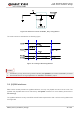
The RESET_N pin can be used to reset the module. The module can be reset by driving RESET_N to a
low level voltage for 150ms~460ms.
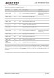
Table 8: Pin Definition of RESET_N
Pin Name Pin No. Description DC Characteristics Comment
RESET_N 17 Reset the module
V
IH
max=2.1V
V
IH
min=1.3V
V
IL
max=0.5V
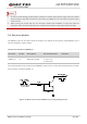
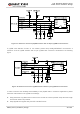
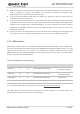
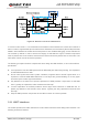
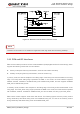
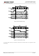
The recommended circuit is similar to the PWRKEY control circuit. An open drain/collector driver or button
can be used to control the RESET_N.
Figure 14: Reference Circuit of RESET_N by Using Driving Circuit
NOTES