
Product Info


LTE-A Module Series
EM06 Hardware Design
EM06_Hardware_Design 13 / 63
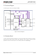
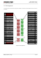
2.3. Functional Diagram
The following figure shows a block diagram of EM06.
Baseband
PMIC
Transceiver
ANT_MAIN
ANT_DIV
ANT_GNSS
APT
VCC
RESET#
19.2M
XO
Control
IQ
Control
Tx
PRx
DRx
PCI Express
M.2 Key
-B Interface
FULL_CARD_POWER_OFF#
W_DISABLE1#
USB2.0&USB3.0
(U)SIM1&(U)SIM2
WWAN_LED#
WAKE_ON_WAN#
NAND +
DDR2 SDRAM
PCM
W_DISABLE2#
GPIOs
Tx/Rx Blocks
Figure 1: Functional Diagram
2.4. Evaluation Board
In order to help customers develop applications conveniently with EM06, Quectel supplies the evaluation
board (M.2 EVB), USB to RS-232 converter cable, USB type-C cable, earphone, antenna and other
peripherals to control or test the module. For more details, please refer to document [1].