
Product Info

LTE Standard Module Series
EG95 Hardware Design
EG95_Hardware_Design 34 / 93
Module
VBAT_RF
VBAT_BB
VBAT
C1
100uF
C6
100nF
C7
33pF
C8
10pF
+
+
C2
100nF
C5
100uF
C3
33pF
C4
10pF
D1
WS4.5D3HV
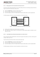
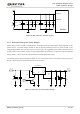
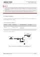
Figure 8: Star Structure of Power Supply
3.6.3. Reference Design for Power Supply
Power design for the module is very important, as the performance of the module largely depends on the
power source. The power supply should be able to provide sufficient current up to 2A at least. If the
voltage drop between the input and output is not too high, it is suggested that an LDO should be used to
supply power for the module. If there is a big voltage difference between the input source and the desired
output (VBAT), a buck converter is preferred to be used as the power supply.
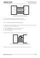
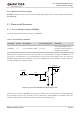
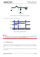
The following figure shows a reference design for +5V input power source. The typical output of the power
supply is about 3.8V and the maximum load current is 3.0A.
DC_IN
MIC29302WU
IN OUT
EN
GND
ADJ
2 4
1
3
5
VBAT
100nF
470uF
100nF
100K
47K
470uF
470R
51K
1%
1%
4.7K
47K
VBAT_EN
Figure 9: Reference Circuit of Power Supply