
Product Info

LTE Standard Module Series
EG95 Hardware Design
EG95_Hardware_Design 39 / 93
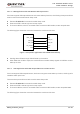
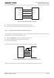
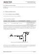
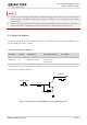
RESET_N
S2
Close to S2
TVS
Figure 15: Reference Circuit of RESET_N by Using Button
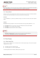
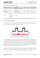
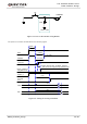
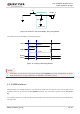
The reset scenario is illustrated in the following figure.
V
IL
≤ 0.5V
V
IH
≥ 1.3V
VBAT
≥ 150ms
Resetting
Module
Status
Running
RESET_N
Restart
≤ 460ms
Figure 16: Timing of Resetting Module
1. Use RESET_N only when turning off the module by AT+QPOWD command and PWRKEY pin failed.
2. Ensure that there is no large capacitance on PWRKEY and RESET_N pins.
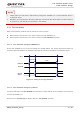
3.9. (U)SIM Interfaces
EG95 provides two (U)SIM interfaces, and only one (U)SIM card can work at a time. The (U)SIM 1 and
(U)SIM 2 cards can be switched by AT+QDSIM command. For more details, please refer to document
[2].
The (U)SIM interfaces circuitry meet ETSI and IMT-2000 requirements. Both 1.8V and 3.0V (U)SIM cards
are supported.
NOTES