
Product Info

LPWA Module Series
BG95 Hardware Design
BG95_Hardware_Design 38 / 88
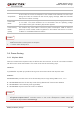
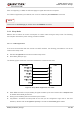
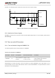
possible. The following figure shows the star structure of the power supply.
Module
VB AT_RF
VB AT_BB
VB AT
C1
100uF
+
+
100nF
33pF
10pF
D1
TVS
100uF
100nF
33pF
10pF
C2 C3
C4
C5 C6 C7
C8
R1 0R
R2 0R
Figure 5: Star Structure of the Power Supply
3.5.3. Monitor the Power Supply
AT+CBC command can be used to monitor the VBAT_BB voltage value. For more details, please refer to
document [2].
3.6. Turn on and off Scenarios
3.6.1. Turn on Module Using the PWRKEY Pin
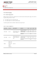
The following table shows the pin definition of PWRKEY.
Table 8: Pin Definition of PWRKEY
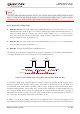
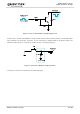
When BG95 is in power off mode, it can be turned on by driving PWRKEY low for 500–1000 ms. It is
recommended to use an open drain/collector driver to control the PWRKEY. A simple reference circuit is
illustrated in the following figure.
Pin Name Pin No. Description DC Characteristics Comment
PWRKEY 15
Turn on/off the
module
Vnorm = 1.5 V
V
IL
max = 0.45 V
The output voltage is 1.5 V because
of the voltage drop inside the
Qualcomm chipset.