
Product Info


5G Module Series
RM510Q-GL Hardware Design
RM510Q-GL_Hardware_Design 38 / 88
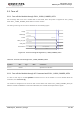
4.1.3. Normally Closed (U)SIM Card Connector
With a normally closed (U)SIM card connector, the USIM_DET is normally short-circuited to ground when
a (U)SIM card is not inserted, and the USIM_DET will change from low to high voltage level when a
(U)SIM card is inserted. The rising edge indicates an insertion of the (U)SIM card. When the (U)SIM card
is removed, USIM_DET will change from high to low voltage level. The falling edge indicates a removal of
the (U)SIM card.
⚫ When the (U)SIM is absent, CD is short-circuited to ground and USIM_DET is at low voltage level.
⚫ When the (U)SIM is inserted, CD is open from ground and USIM_DET is at high voltage level.
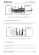
The following figure shows a reference design of (U)SIM interface with a normally closed (U)SIM card
connector.
Module (U)SIM Card
Connector
USIM_DET
USIM_DATA
USIM_CLK
RST
CLK
CD
IO
USIM_VDD
USIM_VDD
USIM_RST
VCC
GND
VPP
GND
TVS
22 Ω
22 Ω
22 Ω
10k-20k
100 nF
33 pF 33 pF 33 pF
Note: All these resistors, capacitors and TVS should be close to (U)SIM card connector in PCB layout.
Figure 15: Reference Circuit for Normally Closed (U)SIM Card Connector
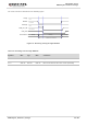
4.1.4. Normally Open (U)SIM Card Connector
With a normally open (U)SIM card connector, the USIM_DET is normally pulled down to ground through
an external resistance when a (U)SIM card is not inserted, and the USIM_DET will change from low to
high voltage level when a (U)SIM card is inserted. The rising edge indicates an insertion of the (U)SIM
card. When the (U)SIM card is removed, USIM_DET will change from high to low voltage level. The falling
edge indicates a removal of the (U)SIM card.
⚫ When the (U)SIM is absent, CD1 is open from CD2 and USIM_DET is at low voltage level.
⚫ When the (U)SIM is inserted, CD1 is pulled up to 1.8 V and USIM_DET is at high voltage level.
The following figure shows a reference design of (U)SIM interface with a normally open (NO) (U)SIM card
connector.