
Use Manual


AT10-2 Use Manual
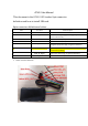
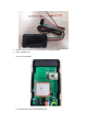
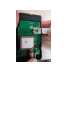
This document is the AT10-2 GPS tracker 8pin connector
definition and how to install SIM card.
8pin connector definition as below:
Item
Pin name
Pin Description
1
GND
Ground
2
VIN_12V
7V~36V Power Input Supply. This supplies power to all the
internal control circuitry
3
RX
The LTE modem RX, 3.3V power domain.
4
TX
The LTE modem TX, 3.3V power domain.
5
GPIO_IGNITION
1x Digital Input (Active High, for Ignition Detection)
6
GPIO_OUT1_RELAY_LOW
Digital Output (Active Low, 150mA Max Drive Current, for
Starter Interrupt Relay)
7
GPIO_IN_Digital
Digital Input (Active High, for Ignition Detection)
8
GPIO_OUT2
General 3.3V GPIO Output
1. AT10-2 connector definition: